AGL
Automotive Grade Linux (AGL) is a collaborative, open-source project that brings together automakers, suppliers, and technology companies for building Linux-based, open-source software platforms for automotive applications that can serve as de facto industry standards. AGL is providing 70-80% starting point for automakers, this is a good option for student to learn about Automotive industry, linux, new technologies and maybe contribute in the future with demos or new features for this platform.
AGL address all software in the vehicle like
- Infotainment
- Instrument cluster
- Heads-up-display (HUD)
- Telematics
- Connected Car
- Advanced driver assistance systems (ADAS)
- Functional safety
- Autonomous driving
- Virtualization Projects
Following this book and getting corresponding mentoring you will be able to understand
- Software version control tool
- Linux system: (Basic) WSL User
- Yocto Project
- Repo tool
- Automotive Grade Linux system
- QT Basic
- CAN
- Code best practices
And able to do in Linux
- Add new services
- Get Logging
- Modify Linux Kernel
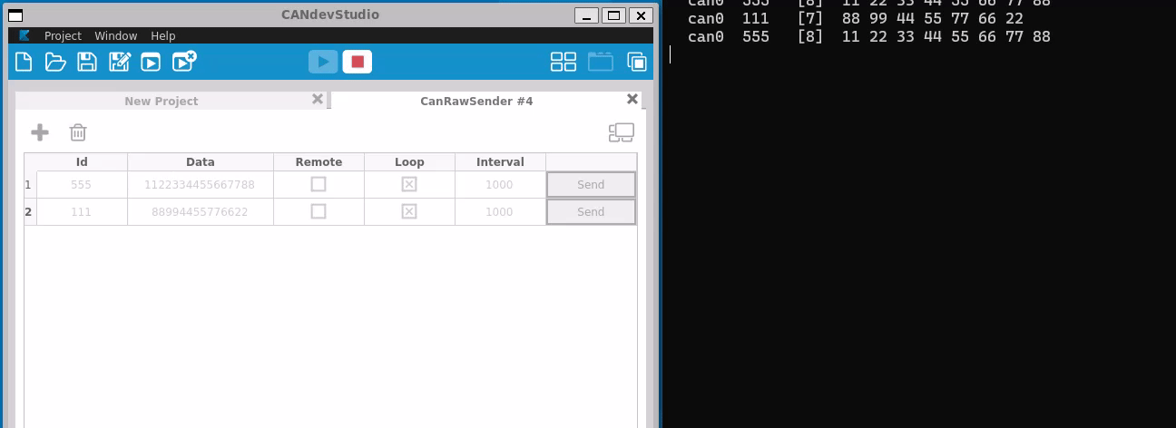
- Implement services can interact with CAN Rx and Tx
- Create Basic QT application for AGL
- Modify Cluster Demo to handled Tachometer, Speedometer and telltales

Project Tool
This section will provide a installation guide for required tools to work with AGL project.
In order to work on the AGL project we will require a set of tools to configure, develop and test all of our system components.
Our basic tool-set will be specific to the case of having Windows OS as the host system, if you have other OS like Ubuntu Linux some of the tools will not be required or will need to be replaced by an alternative tool.
Basic Tool-set includes: - WSL (Windows Subsystem Layer) - Putty (Serial and SSH Client) - QT (GUI framework) - Virtual Box
You will find more information about each tool and how to setup and configure
for the project on the next sections.
WSL
What is WSL?
The Windows Subsystem for Linux lets developers run a GNU/Linux environment -- including most command-line tools, utilities, and applications -- directly on Windows, unmodified, without the overhead of a virtual machine or dual boot setup.
See complete overview WSL
Why WSL
WSL is a easy way to learn, understand and develop on linux without any need to spend time installing linux in your host machine, the process to install and use is simple and you can use most of the host resources, share files and tools between windows and Linux.
If we compare with Linux running directly host, we will have lower performance in WSL than the same distribution running directly on host, this is expected as WSL is running virtualized on top of windows and sharing resources between both OS.
We choose WSL for starting point, as you will see how easy is to start working in Linux following the steps described in next chapters.
Start with WSL
WSL have 2 different versions WSL1 and WSL2, we will use WSL2 as this version is already tested for AGL.
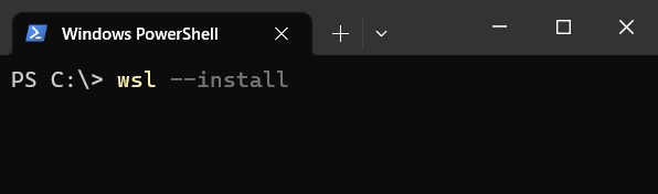
Starting installation is simple you just need open CMD, powershell or Terminal windows go with either one of the options below:
a) Use specific distribution
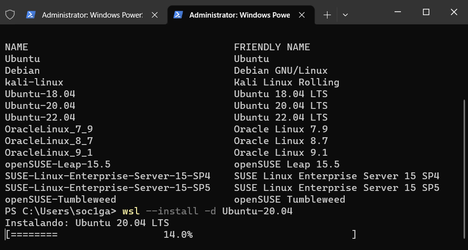
First check the available distribution using below command
wsl --list --online

Then type below command to install Ubuntu-20.04
wsl --install Ubuntu-20.04

b) Use Ubuntu by default then type this command
wsl --install
See official page for more details.
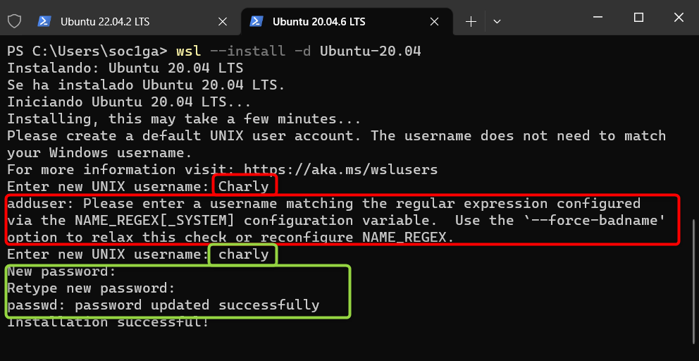
After previous commands you will see the installation progress like this
Once this process completes you need provide user and password, for user name use lowercase, if you use uppercase for user will get an error like in the red rectangles. Accepted entry will ask for password again, then installation will be completed.
WSL Configuration
WSL use 2 files to set it's own configuration, the complete description of each configuration is available at this place: wsl-config
1.- Internally to our Ubuntu \etc\wsl.conf, please create this file and add the below text
wsl.conf content:
# Set a command to run when a new WSL instance launches.
[boot]
systemd=true
2.- Externally in Windows C:\Users\your-user.wslconfig .wslconfig content: NOTE: memory, processors and swap options need to be adapted base on your PC
# Settings apply across all Linux distros running on WSL 2
[wsl2]

# Memory to assign to the WSL2 should not excede 80% of total RAM memory
memory=12GB

# How many processors to assign to the WSL2
processors=8

# Sets amount of swap storage space, default is 25% of available RAM
swap=8GB

# Sets swapfile path location, default is %USERPROFILE%\AppData\Local\Temp\swap.vhdx
swapfile=C:\\temp\\wsl-swap.vhdx

# Disables nested virtualization
nestedVirtualization=true

# Turns on output console showing contents of dmesg when opening a WSL 2 distro for debugging
debugConsole=false

#Boolean to turn on or off support for GUI applications (WSLg) in WSL.
guiApplications=true
Now restart WSL with this command in windows terminal and after 8 second open new terminal
wsl --shutdown
First Command in WSL
Open Ubuntu terminal in your windows OS and we will start to use our distribution
Update all components from Ubuntu distro and upgrade the system
sudo apt-get --assume-yes update && apt-get --assume-yes upgrade && apt-get clean
Install some useful packages
sudo apt-get --assume-yes install curl nano wget apt-transport-https ca-certificates rsync filepp device-tree-compiler cmake libgtest-dev google-mock gcovr lcov pandoc mc texlive-fonts-recommended texlive-latex-recommended libc6-dev libxml2-dev libicu-dev git-core gnupg flex bison gperf build-essential zip curl zlib1g-dev gcc-7-multilib g++-7-multilib x11proto-core-dev libx11-dev ccache tofrodos gawk ant libxml2-utils libgl1-mesa-dev xsltproc unzip libssl-dev liblz4-tool openjdk-8-jdk libc6-dev-i386 lib32z-dev bc gettext u-boot-tools libjson-perl libterm-readkey-perl libmime-lite-perl libarchive-zip-perl libtext-glob-perl xmlstarlet jq adb fastboot sloccount dstat android-sdk-libsparse-utils android-sdk-ext4-utils python3.7 libncurses5 gawk wget git diffstat unzip texinfo gcc chrpath socat cpio python3 python3-pip python3-pexpect xz-utils debianutils iputils-ping python3-git python3-jinja2 libegl1-mesa libsdl1.2-dev pylint3 xterm python3-subunit mesa-common-dev
Try use the below commands in WSL:
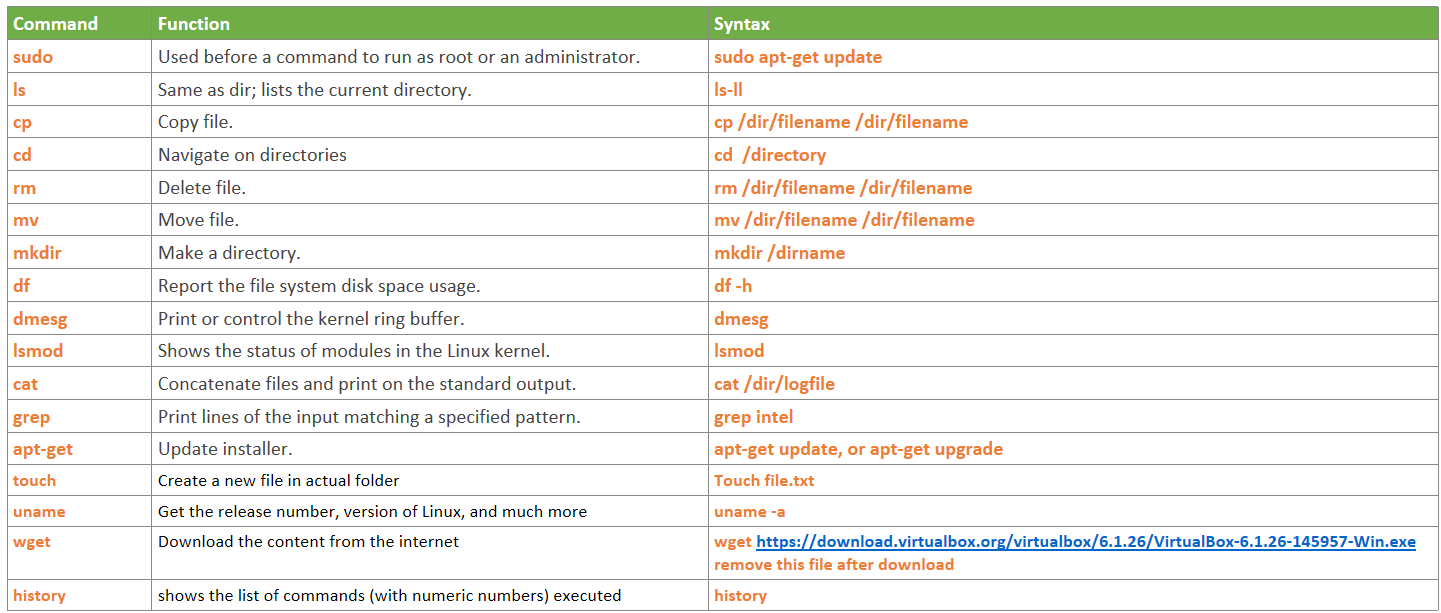
Learn more about Linux command line.
Backup WSL
I recommend after all tool installation and before start work with any project in WSL create a Backup and store it in safe location, in this way you can recover your WSL state, avoiding spending time installing all the tools again. WSL have 2 command for this export and import command
Backup Command:
wsl --export Ubuntu-20.04 path/where/save/backup/Ubuntu-20.04_backup.tar
Backup Recovery Command:
wsl --import Ubuntu-20.04 C:\Users\<username\AppData\Local\Packages\Ubuntu-20.04 path/where/save/backup/Ubuntu-20.04_backup.tar
Alternatives to WSL
In case WSL is not working, you can still use Ubuntu in Virtual box, just follow the Virtual Box installation steps
Warning: virtual machine require minimum 200GB storage space for project, please consider it during storage creation.
Virtual Box
What is VirtualBox?
VirtualBox is a general purpose virtualizer that is available for different OS.
VirtualBox installation
-
Download Virtual Box from VirtualBox Website.
-
Follow the installation steps and once is completed you will see something like below:

Putty
What is Putty?
PuTTY is a free and open-source terminal emulator, serial console and network file transfer application, this tool will be required to communicate with the OS from Cluster project.
Putty installation
-
Download Putty from Putty Website and follow installation steps.
-
Once you complete the installation open Putty and will looks like below image, we will use it once we runs first project demo.

QT Tool
What is QT?
Qt is a framework used for GUI development and we will use it for one of the core technologies for our software. Qt is a C++ framework that supports the WOCA (Write Once, Compile Anywhere) principle, which means Qt is a cross-platform framework.
It’s mainly used to develop applications and graphical user interfaces (GUIs) that can run across different operating systems.
Qt framework provides such collaboration tools as Qt Creator, Qt Quick, Qt Design Studio, and others. You can quickly build future-proof projects using Qt with fewer feedback loops and more efficient iterations.
There’s also a specific software development language for user interface-focused apps offered by Qt, which is called Qt Modeling Language (QML). It can be used with Java, Python, Go, PHP, Ruby, and other programming languages.

Git
What is git?
The first thing you will hear about git is that "Git is a distributed version control system" so lets start by understanding what is a Version Control Systems(VCS).
A Version Control System records changes to a file or set of files over time so that you have a history of them. An example of a VCS that you most likely already use is Word, Word has built-in feature "track changes" that allows us to visualize differences between 2 file versions; although hopefully by now you know that Word is rather slow and only works for its own files, so here we will see a faster and optimized tool for multiple file types. In contrast, a well designed VCS has the following features:
- Revert selected files back to a previous state, or even the entire project back to a previous state.
- Compare changes between any 2 versions.
- See who last modified something that might be causing a problem, who introduced an issue, when, and more. Using a VCS also generally means that if you screw things up or lose files, you can easily recover.
Distributed VCS
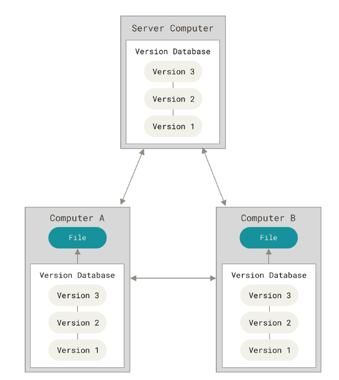
Distributed Version control system means that every collaborator(any developer working on a team project)has a local repository of the project in his/her local machine which allow for faster and offline work possible,
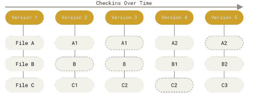
Storing files: snapshots vs deltas
Unlike most of the VCS that store file versions as Deltas(changes applied to a base file), Git stores SNAPSHOTS of all the files in the repository(unless file is identical, then it only links the last one). This decision will be clearer when we explain git branching; but for now, know that these copies make comparisons faster and they also get compressed so no need to worry too much about the size.
Furthermore, git has integrity check via 40 character SHA-1 hash, over the contents of each commit.
Lifecycle of file status
Below you can see the 4 states of our files and the commands by which they change, these states exist to organize our files and only push files that we want everyone else to see:
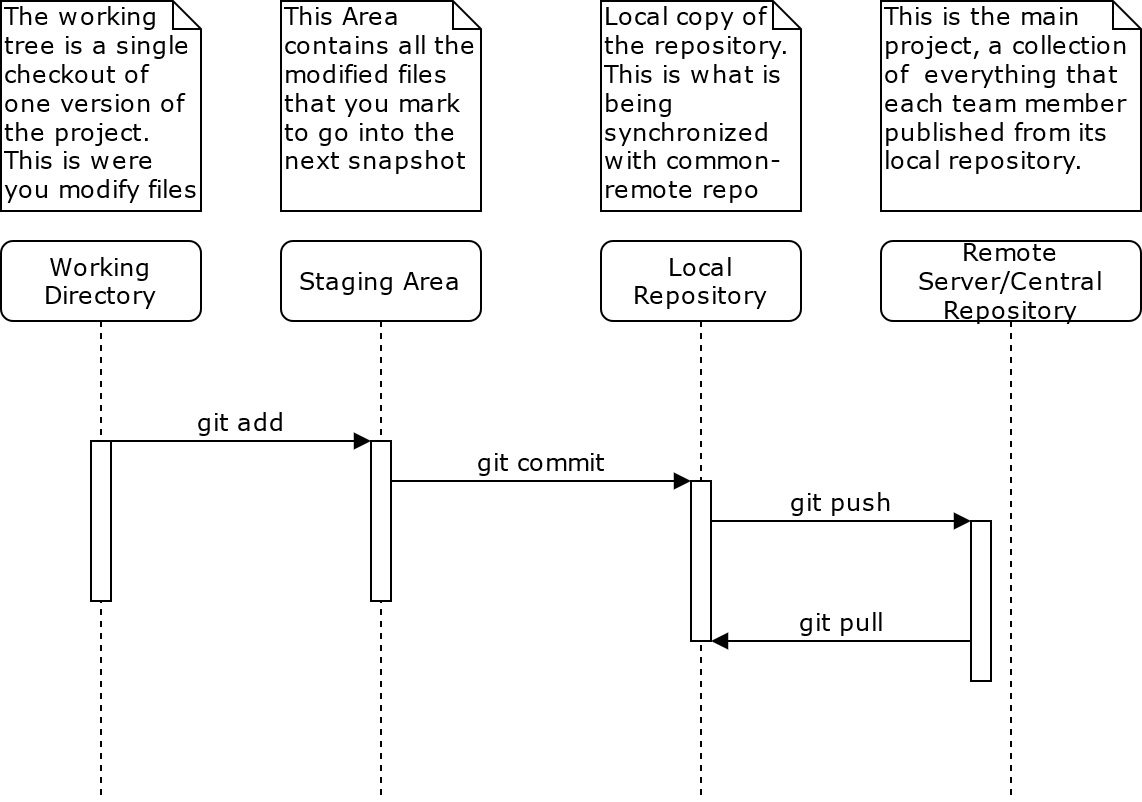
Note that, since we own a copy of the repository nearly all operations are local, except for synchronizing changes with the main server which make your changes visible to everyone else.
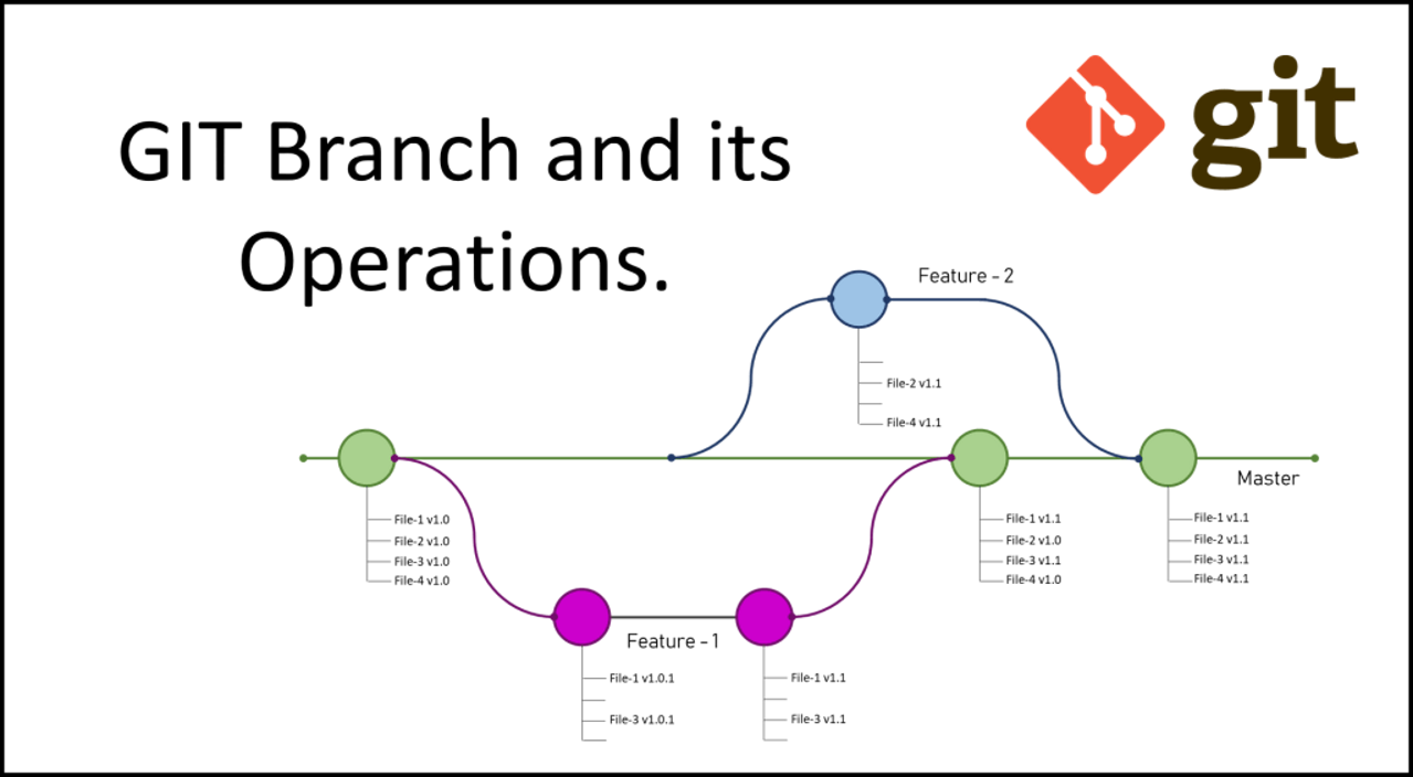
Git branching
Branching means you diverge from the main line of development and continue to do work without messing with that main line. Commonly mainline refers to whats is in production, or already working, and to branch means to make a "shallow copy" of the current snapshot as a base for a new line of development. Branching looks like this:

Reading more
To understand more about git its recommended to read the official book.
To practice branching my personal recommendation is this website: learn git branching
Getting started
Setting up a repository
There are many ways to install git for windows, and many GUI's... but the most basic is to download git directly from Git website: https://git-scm.com/download/win.
As for Linux, you can just download the package from package manager:
sudo apt-get git
There is a first-time-only setup(git config) that allows to store your custom configuration variables and profile(user, email) for all repositories that you work on. So don't forget to run the setup commands on the cheat sheet .
Now lets create or clone a repository:
- git init → This takes you current directory and turns it into a git repository by creating a new subdirectory named .git that contains all the necessary repository files for git.
- git clone
→ Gets a copy of an existing Git repository. Git receives a full copy of nearly all data that the server has.
Recording changes in a repository
Lets play!!! Try to add or modify a couple of files and store those changes in your local repository. Below is a list of commands that will be useful:
- git add → is a multipurpose command — you use it to begin tracking new files, to stage
files, and to do other things like marking merge-conflicted files as resolved. It may be helpful to think of it more as “add precisely this content to the next commit”.
- -A stages all changes stages new files and modifications, without deletions
- -u stages modifications and deletions, without new files
- git commit → saves the changes made(staged files) into the local repository.
- -m inline commit message
- -a commit includes all modified files, letting you skip the git add
- --amend redo that commit, make the additional changes you forgot, stage them, and commit again
- git push → upload your changes to the remote server
- git status → determine which files are in which state(remember de lifecycle of file status)
- -s or --short, get simplified output of the state of files
- git diff → shows you the exact lines changed (added and removed), but not yet staged.
- --staged or --cached. This command compares your staged changes to your last commit
- git log → View commit history: lists the commits made in that repository from most recent to oldest
ACTIVITY TIME: Simple calculator
With the commands mentioned in the past pages we can start working on our first versioned project. Now assume you found an interesting code for a simple calculator(calculator.c). Note: Remember to compile it as $gcc calculator.c -o executable-Name
    #include <stdio.h>

    void add ();
    void sel_func (int);

    int main (void)
    {
            int s;

            Input:
            printf("Select the number of calculator operation [ 1-sum ] : ");
            scanf("%d",&s);

            if (s > 1 | s < 1){
                    printf("Please select a valid operation\n");
                    goto Input;
            }
            sel_func (s);

            goto Input;
    }

    void sel_func (int s)
    {
            void (*fptr)(void);
            switch (s){
            case 1:
                    fptr = add;
                    break;
            }

            fptr();
    }

    void add ()
    {
            int a, b;

            printf("Input two numbers : \n");
            scanf("%d%d", &a, &b);
            printf("Result = %d\n", a + b);
    }
Lets create a new repository and add this as the first commit. Hints:
- Check/update your user/email configuration(only on first time)
- Add calculator.c
Incremental change 1
Our first calculator only has the addition operation but we want to multiply as well.
Incremental change 2
Style changes:
- goto should not be used, modify it
- readability
Incremental change 3
Modular calculator:
- Divide calculator in different files for maintainability.
- Make any other improvement that adds value to a good design pattern.
Mini project: Parser
Work in groups of 2
Person 1: text-to-morse
Create a parser that reads input from a file and prints the corresponding morse code. For example, the input "hello world" should give the output:
.... . .-.. .-.. --- / .-- --- .-. .-.. -..
Allow at least 1024 characters.
Person 2: morse-to-output
Take a morse code as an input and communicate it by any means: audio, light, vibrations...
dit = 1 unit
dah = 3 units
intra-character space = 1 unit
inter-character space = 3 units
word space = 7 units
- Note: the unit time must be adjustable.
- The time for testing will be 5, 10 and 20 WPM using the word PARIS as reference, in case of 5WPM this is equivalent to: 10 dits * 1 unit = 10 4 dahs * 3 units = 12 9 intra-characters * 1 unit = 9 4 inter-character * 3 units = 12 1 word space * 7 units = 7 = 48 units per PARIS word. So for 5 WPM we have 240 units, meaning a unit is 0.25s
Points
- Faster implementation: time to execute the whole workflow from text to output
- Smaller implementation: size of executable fits in less memory space
- Best architecture: good design, follows KISS and SOLID design principles.
- Obfuscated impementation: normally not good but in this case we want to prize creativity
- Features: goes beyond than parsing and outputting the code.
- Effective communication: a message will be given and whoever group that communicates the message first from one member to another is the winner.
- Preciseness: follows time units precisely.
Repo
Repo is a tool built on top of Git, Repo helps manage many Git repositories, does the uploads to revision control systems, and automates parts of the development workflow. Repo is not meant to replace Git, only to make it easier to work with Git. The repo command is an executable Python script that you can put anywhere in your path.
Repo Project
Repo use an artifactory to crate a repo project defining the folder structure and the different git repositiries and it specific version used by this project, this artifactory is called repo manifest

A repo manifest describes the structure of a repo client; that is the directories that are visible and where they should be obtained from with git. The basic structure of a manifest is a bare Git repository holding a single default.xml XML file in the top level directory. Manifests are inherently version controlled, since they are kept within a Git repository. Updates to manifests are automatically obtained by clients during repo sync.
Installation
Use the below commands to install repo in your Linux distribution
mkdir -p ~/.bin
PATH+=:~/bin
curl https://storage.googleapis.com/git-repo-downloads/repo  ~/.bin/repo
chmod a+rx ~/.bin/repo
echo 'PATH+=:~/bin'  ~/.bashrc
See complete information in Repo website.
Command Repo
Repo tool have a set of commands, using the below command after repo tool install you will see complete list of Repo commands
repo help
Example output
The complete list of recognized repo commands is:
  abandon        Permanently abandon a development branch
  branch         View current topic branches
  branches       View current topic branches
  checkout       Checkout a branch for development
  cherry-pick    Cherry-pick a change.
  diff           Show changes between commit and working tree
  diffmanifests  Manifest diff utility
  download       Download and checkout a change
  forall         Run a shell command in each project
  gitc-delete    Delete a GITC Client.
  gitc-init      Initialize a GITC Client.
  grep           Print lines matching a pattern
  help           Display detailed help on a command
  info           Get info on the manifest branch, current branch or unmerged branches
  init           Initialize a repo client checkout in the current directory
  list           List projects and their associated directories
  manifest       Manifest inspection utility
  overview       Display overview of unmerged project branches
  prune          Prune (delete) already merged topics
  rebase         Rebase local branches on upstream branch
  selfupdate     Update repo to the latest version
  smartsync      Update working tree to the latest known good revision
  stage          Stage file(s) for commit
  start          Start a new branch for development
  status         Show the working tree status
  sync           Update working tree to the latest revision
  upload         Upload changes for code review
  version        Display the version of repo
See 'repo help <command>' for more information on a specific command.
Create Repo Project
Create your own AGL repository, first steps is create a new folder inside you folder user in WSL then inside this folder from command line type the next command, this will take some time depend of your connectivity
repo init -u https://gerrit.automotivelinux.org/gerrit/AGL/AGL-repo
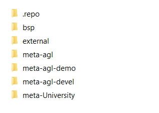
Once process is completed explore .repo folder, this is a hide folder but if the previous command completed successfully folder is there, each time you create a new repo this folder will exist, you will see something like below
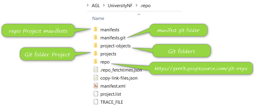
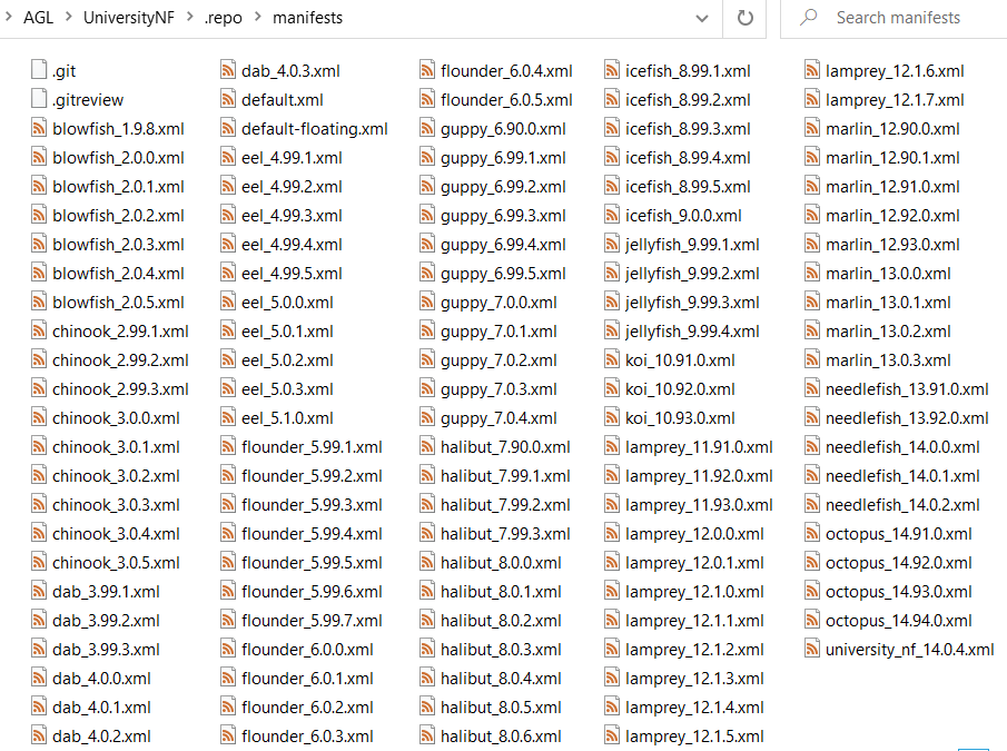
Each folder have a specific usage but now you will focus on manifests folder, this folder is a git repository and inside you will see a complete set of XML files each file is a manifest file, you will see
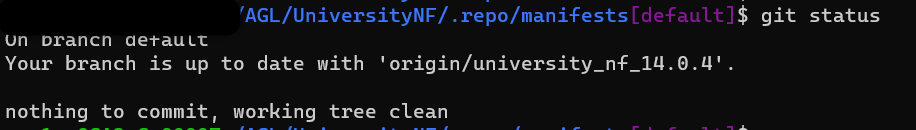
From command line we can run next command to see the repository status
git status
Output will looks like this
As you can see Repo contain a git repository with multiple manifest and each manifest is a project configuration o version project, if we need select a specific manifest for our usage we need use below command, in this case we will use
repo init -m needlefish_14.0.2.xml
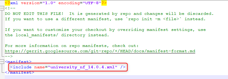
If you want to now which manifest you are using check manifest.xml file from ".repo" folder, Inside file you will find the repo project manifest used, below is an example of manifest.xml file
After this small navigation from Repo folder we need to get our repo project, for that we must use next command, this will create folder structure defined in manifest and the corresponding git repository inside
repo sync
Someting like below structure will be available a t the end of repo sync
Repo Branch
Repo Branch use same concept from Git Branch a Git branch is a new/separate version of the main repository.
Example you have a large project and you have multiple updates at same time, how would that work with branches:
• Create a new branch called new-design, edit the code directly without impacting the main branch
• EMERGENCY! There is an unrelated error somewhere else in the project that needs to be fixed ASAP!
• Create a new branch from the main project called small-error-fix
• Fix the unrelated error and merge the small-error-fix branch with the main branch
• You go back to the new-design branch, and finish the work there
• Merge the new-design branch with main (getting alerted to the small error fix that you were missing)
Branches allow you to work on different parts of a project without impacting the main branch. When the work is complete, a branch can be merged with the main project. You can even switch between branches and work on different projects without them interfering with each other.
Branches in Repo
At this point you already create a repo and sync the project now to work with Branches using Repo next commands will help
To start a topic branch
repo start branchname --all
To verify that your new branch was created
repo status
Output
Using topic branches To assign the branch to a particular project
repo start branch name project
Project can be listed using
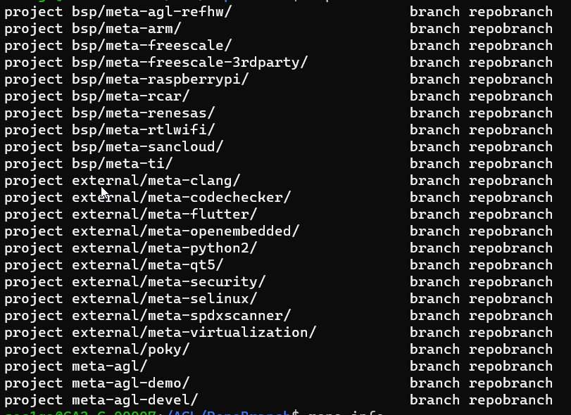
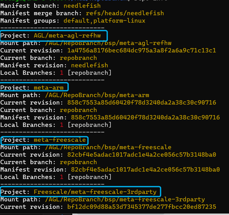
repo info
To switch back and forth among branches that you have created in your local work environment
git checkout branchname
To see a list of existing branches:
git branch
or...
repo branches
The name of the current branch will be preceded by an asterisk
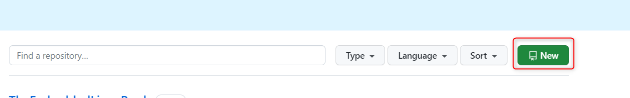
Create own Repo Project Branch
Is time to create a own repo project branch, first we have to enter in ".repo\manifest" folder, this folder contain the git repository with multiple manifest.
Type the below commands to see a complete list of Branches from git manifest repository
git branch -a
Next step is create our own Branch, use next command
git checkout -b UniTestBranch
Next step is t print all the files in this folder we will use like reference
la
Create a new manifest file using exiting manifest project
cp needlefish_14.0.4.xml needlefish_14.0.4_University.xml
Check if new files was created successfully
ls
We would like to save the new branch with new manifest to start working in out account, for this next steps are required
Create commit and be ready to push
From GitHub create a empty repository
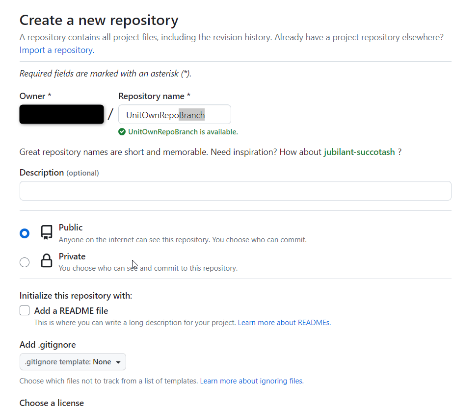
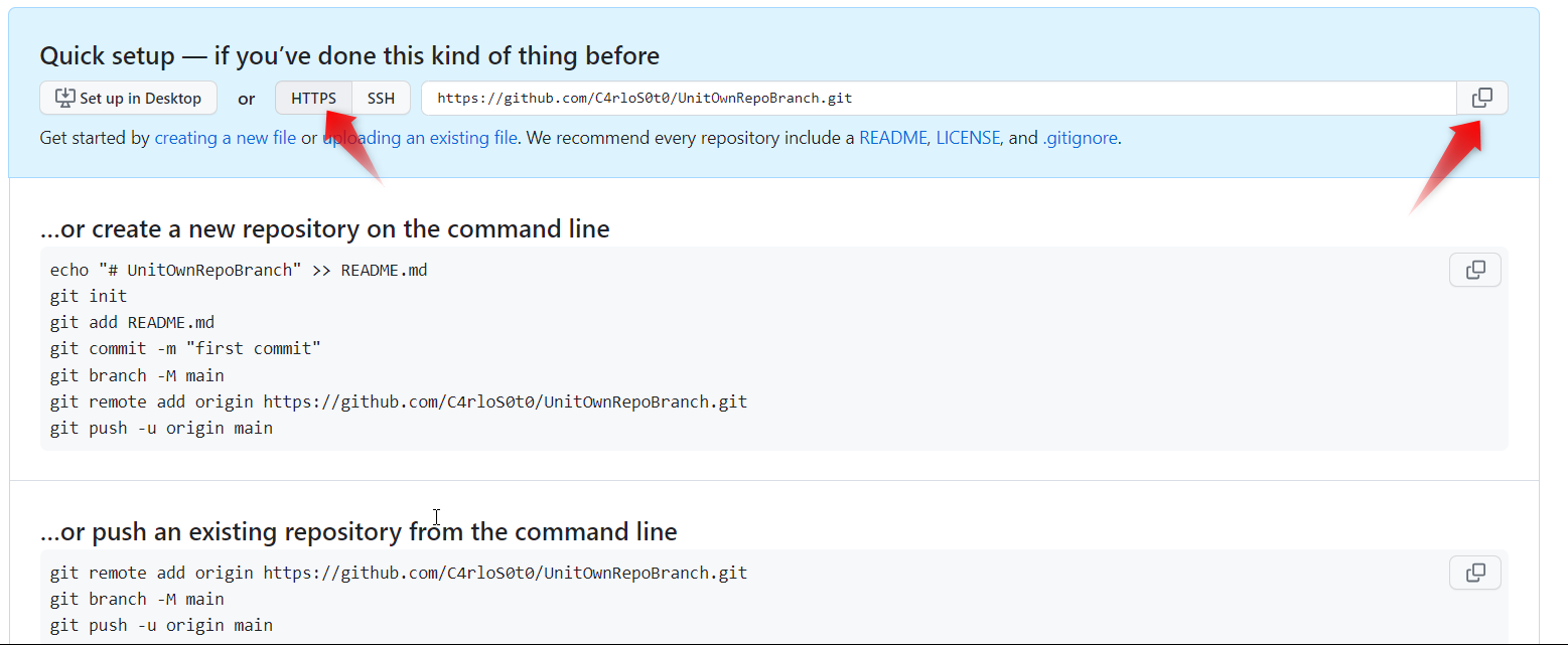
git push --all -u https://github.com/gitUser/UnitOwnRepoBranch.git
#Activity
Branch
Find, Create and document 2 different methods to create Branches for repo tool
Manifest
Add a new GIT repository in your own manifest, the goal is have your repository available one you call repo syncThe Linux system
A short Timeline of computer advancements:
1945-1955 vacuum tubes and punching cards.
1955-65: Transistors and batch systems:
Batch systems accumulate many jobs into tape and run all the tape at once. Separation between designers, operators, programmers(assembly or FORTRAN) and maintenance.
1965-80: ICs, multi programming and the birth of UNIX and Microsoft:
In the 1960s, Moore’s Law predicted that the number of transistors on an integrated circuit would double every eighteen months. The IBM 360 (A family of compatible computers that ranged from low to high performance were built to satisfy the growth of the programs of the client), had the goal achieving compatibility of programs across the family of computers that share the same architecture, however that required that the piece of code called "operating system" meet all the conflict requirements for scientific and commercial environments, which obviously resulted in thousands of bugs in assembly code; but managed to satisfied most of the customers reasonably well. They popularized several key techniques like the multi programming to keep computer working 100% of the time by keeping 3 jobs on different memories, utilizing the idle time that the CPU waited for IO for another job.
1974: 8080 First general-purpose 8-bit Intel CPU.
Kildall wrote the OS and found Digital Research, but a killing decision of not writing an OS for IBM in 1980 led Seattle Computer Products to create DOS(Disk Operating System) and Bill Gates hired Tim Patterson to revise it, becoming MS-DOS.
Doug at Stanford Research did some research on GUI's and Xerox PARC adopted into the machines they built, Steve Jobs saw them and embarked on building an Apple with a GUI(LISA). Second attempt succeeded because it was user friendly, meaning that it was intended for users who not only knew nothing about computers but furthermore had absolutely no intention whatsoever of learning. Apple inspire Windows 95, the first freestanding version of a GUI built into a modified MS-DOS.
MULTICS was developed as a way to share a computer across multiple users(yes this is where cloud computing started) and it was a success because people knew how to write small, efficient programs(a skill that has been lost). However this effort did not take over the world because it was written in PL/I which was an obsolete compiler but many discoveries helped to develop UNIX OS. UNIX began with a MULTICS version and grew into multiple incompatible versions, which led to the development of the POSIX standard by the IEEE that standardizes interfaces to run a program into any UNIX system.
1980-Present: Personal Computers MINIMIX(1987) and Linux
The detection and replacement of faulty/crashed modules on the fly without a reboot or disturbing running programs was its goal: reliability, dependability and availability. This system is described on Operating Systems Design and implementation (Tanenbaum & Woodhull).
MINIMIX led to Linux, a free production OS created by Linus Torvalds. With the development of Large Scale Integration circuits, chips containing thousands of transistors, personal computers became affordable.
The Unix OS
UNIX, is a family of operating systems that derive or behave like AT&T Unix(1969). Unix and Unix-like Operating Systems have been standardized to comply with POSIX standard. The main features of Unix that allowed it to create general-purpose reusable/modular programs that can be combined to create the first "scripting language" that enable us to produce complex workflows are:
- tree filesystem
- file descriptors
- pipes
- shell syntax operations
AT&T Archives: The UNIX Operating System
Linux Overview
Linux is commonly used to refer to the entire UNIX-like operating system of which the Linux kernel forms a part.
Linux System Architecture
Add picture
The physical machine, the bottom or base of the system, made up of memory (RAM) and the processor or central processing unit (CPU), as well as input/output (I/O) devices such as storage, networking, and graphics. The CPU performs computations and reads from, and writes to, memory.
Linux Kernel
The Linux Kernel is a free and open-source, monolithic, modular, multitasking UNIX-like operating system kernel. It is the core interface between a computer’s hardware and its process. It communicates between the two, managing resources as efficiently as possible.
The Linux kernel executable typically resides at the pathname /boot/vmlinuz.
The kernel performs the following tasks:
- Process management: determine which processes can use the central processing unit (CPU), when and for how long.
- Memory management: keep track of how much memory is used to store what and where.
- Provision of a file system: allow files to be created, retrieved, updated, deleted and so on.
- Creation and termination of processes: permit load a new program into memory, providing it with the resources that it needs to run. When a process ha completed the execution, the kernel ensures that the resources it uses are freed for subsequent reuse by later programs.
- Device drivers: acts as intermediary between the hardware and processes.
- Networking: transmits and receives network messages on behalf of user processes.
- Provision of a system call application programming interface (API): process can request the kernel to perform various tasks using kernel entry points known as system calls.
The kernel resolves potential conflicts in accessing hardware resources, so users and processes are generally unaware of the conflicts.
Kernel mode and user mode
The processor architectures typically allow the CPU to operate in at least two different modes:
- User Mode: the CPU can access only memory that is marked as being in user space; attempts to access memory in kernel space results in a hardware exception.
- Kernel Mode: the CPU can access both user and kernel memory space.
Shell
A shell, known as a command interpreter, is special-purpose program designed to read commands typed by a user and execute appropriate programs in response to those commands. The shell is a user process. The shell are designed not merely for interactive use, but also for the interpretation of shell scripts, which are text files with shell commands. Types of shells:
- Bourne shell (sh)
- C shell (csh)
- Korn shell (ksh)
- Bourne again shell (bash)
Users and Groups
Each user on the system is uniquely identified, and users may belong to groups.
Users
Each user has a unique username and user ID (UID). The password file, /etc/passwd, includes the following information for each user:
- Username
- Password: It is set as x in this file and stored in the /etc/shadow file.
- User ID
- Group ID
- Full name of the user
- Home Directory: initial directory into which the user is placed after logging in.
- Login shell: name of the program to be executed to interpret user commands.
- Add image
Groups
The users are organized into groups, for controlling access to files and other system resources. The group file, /etc/group, includes the following information for each group:
- Group name
- Group ID (GID)
- User list
- Add image
Superuser
The superuser has special privileges within the system. Its user ID is 0 and has the login name root. It bypasses all permission checks in the system. The system administrator uses the superuser account to perform various administrative tasks on the system.
Directory Hierarchy, Directories, Links and Files.
The kernel maintains a single hierarchical directory structure to organize all files in the system. At the base of this hierarchy is the root directory (/). All files and directories are children or further removed descendants of the root directory.
File Types
Each file is marked with a type, indicating what kind of file it is. One file could be regular or plain, devices, pipes, sockets, directories, and symbolic links.
Directory and links
A directory is a file whose contents take the form of a table of filenames coupled with references to the corresponding files. This filename-plus-reference association is called a link. A file may have multiple links, and thus multiple names, in the same or different directories. Directories may contain links both to files and to other directories.
Symbolic link
A symbolic link provides an alternative name for a file. It has a filename-plus-pointer entry in a directory, and the file referred to by the pointer contains a string that names another file.
File ownership and permissions
The ownership of a file is used to determine the access rights available to users of the file. The system divides users into three categories: the owner of the file, users who are members of the group ID, and others. Three permission bits may be set for each of these categories: read, write and execute.
- Add image
File I/O Model
The same system calls are used to perform I/O on all types of files, including devices. The kernel translates the application’s I/O requests into appropriate filesystem or device-driver operations that preform I/O on the target file or device.
Programs
The programs normally exist in two forms: source code and binary. The two forms are considered synonymous since the step of compiling and linking converts source code into semantically equivalent binary machine code.
Process
A process is an instance of an executing program. When a program is executed, the kernel load the code of the program into virtual memory, allocates space for program variables, and sets up kernel bookkeeping data structures to record various information about the proves.
A process is logically divided into the following parts, known as segments:
- Text: the instructions of the program.
- Data: the static variables used by the program.
- Heap: an area from which programs can dynamically allocate extra memory.
- Stack: a piece of memory that grows and shrinks as functions are called and return and that is used to allocate storage for local variables and function call linkage information.
Each process has a unique integer process identifies (PID). Each process also has a parent process identifies (PPID), which identifies the process that requested the kernel to create this process. A process can terminate in one of two ways: by requesting its own termination or by being killed by the delivery of a signal.
Bootloader
The bootloader is responsible for loading the kernel and initial ramdisk before initiating the boot process. It is a piece of software started by the firmware (BIOS or UEFI). It is responsible for loading the kernel with the wanted kernel parameters and any external initramfs images.
Init System
Init is the first process started during booting of the operating system and runs until the system shuts down. It is the process ID 1. Its role is to create process from script stored in the /etc/inittad which is a configuration file which is to be used by initialization system. It is the latest step of the kernel in the boot sequence.
Daemons
A daemon is a process with the following characteristics:
- It is long-lived. It is common that the daemon is created at system startup and runs until the system is shut down.
- It runs in the background and has not controlling terminal. It ensures that the kernel never automatically generates any job-control or terminal-related signals, i.e. SIGINIT, SIGTSTP, SIGUP for a daemon.
Daemons are written to carry out specific tasks, for example:
- cron: exectues commands at a schedule time.
- sshd: secure shell daemon, to login from remote hosts using a secure communications protocol.
- httpd: HTTP server daemon, which server web pages.
- inetd: Internet superserver daemon, which listens for incoming network connectionsn on specified TCP/IP ports and launches appropriate server programs to handle these connections.
SystemD
SystemD is a system that is designed for the Linux Kernel.
SystemD is a suite of basic building blocks for a Linux system. As it replaces the sysvinit process to become the first process, that runs as PID1 and starts the rest of the system.
SystemD provides aggressive parallelization capabilities, uses socket and D-Bus activation for starting services, offers on-demand starting of daemons, keeps track of processes using Linux control groups, maintains mount and automount points, and implements an elaborate transactional dependency-based service control logic.
SystemD also includes a logging daemon, utilities to control basic system configuration like the hostname, data, locale, maintain a list of logged-in users and running containers and virtual machines, system accounts, runtime directories and settings, and daemons to manage simple network configuration, network time synchronization, log forwarding, and name resolution.
SystemD provides support for automatically reverting to the previous version of the OS or kernel in case the system consistently fails to boot.
Add Image
Logging
Syslog
The syslog provides a single, centralized logging facility that can be used to log messages by all applications on the system.
- Add Image
The syslog has two principal components: the syslogd daemon and the syslog library function.
SocketCAN
The socketcan package is an implementation of CAN protocols (Controller Area Network) for Linux. CAN is a networking technology which has widespread use in automation, embedded devices, and automotive fields.SocketCAN uses the Berkeley socket API, the Linux network stack and implements the CAN device drivers as network interfaces. The CAN socket API has been designed as similar as possible to the TCP/IP protocols to allow programmers, familiar with network programming, to easily learn how to use CAN sockets.
Main goal of SocketCAN is to provide a socket interface to user space applications which builds upon the Linux network layer. In contrast to the commonly known TCP/IP and ethernet networking, the CAN bus is a broadcast-only medium that has no MAC-layer addressing like ethernet. The CAN-identifier (can_id) is used for arbitration on the CAN-bus. Therefore the CAN-IDs have to be chosen uniquely on the bus. When designing a CAN-ECU network the CAN-IDs are mapped to be sent by a specific ECU. For this reason a CAN-ID can be treated best as a kind of source address.
This chapter is an extraction of the kernel documentation and will explain basic implementation of SocketCan, to see complete documentation please enter here: Kernel Docs
How to use SocketCAN
Like TCP/IP, you first need to open a socket for communicating over a CAN network and pass PF_CAN as the first argument to the socket system call. Currently, there are two CAN protocols to choose from, the raw socket protocol and the broadcast manager (BCM). So to open a socket, you would write:
s = socket(PF_CAN, SOCK_RAW, CAN_RAW);
and:
s = socket(PF_CAN, SOCK_DGRAM, CAN_BCM);
respectively. After the successful creation of the socket, you would normally use the bind system call to bind the socket to a CAN interface. After binding (CAN_RAW) or connecting (CAN_BCM) the socket, you can read and write from/to the socket or use send, sendto, sendmsg and the recv* counterpart operations on the socket as usual. There are also CAN specific socket options described below.
The Classical CAN frame structure (aka CAN 2.0B), the CAN FD frame structure and the sockaddr structure are defined in include/linux/can.h:
struct can_frame {
        canid_t can_id;  /* 32 bit CAN_ID + EFF/RTR/ERR flags */
        union {
                /* CAN frame payload length in byte (0 .. CAN_MAX_DLEN)
                 * was previously named can_dlc so we need to carry that
                 * name for legacy support
                 */
                __u8 len;
                __u8 can_dlc; /* deprecated */
        };
        __u8    __pad;   /* padding */
        __u8    __res0;  /* reserved / padding */
        __u8    len8_dlc; /* optional DLC for 8 byte payload length (9 .. 15) */
        __u8    data[8] __attribute__((aligned(8)));
};
Remark: The len element contains the payload length in bytes and should be used instead of can_dlc. The deprecated can_dlc was misleadingly named as it always contained the plain payload length in bytes and not the so called 'data length code' (DLC).
To pass the raw DLC from/to a Classical CAN network device the len8_dlc element can contain values 9 .. 15 when the len element is 8 (the real payload length for all DLC values greater or equal to 8).
The alignment of the (linear) payload data[] to a 64bit boundary allows the user to define their own structs and unions to easily access the CAN payload. There is no given byteorder on the CAN bus by default. A read(2) system call on a CAN_RAW socket transfers a struct can_frame to the user space.
The sockaddr_can structure has an interface index like the PF_PACKET socket, that also binds to a specific interface:
struct sockaddr_can {
        sa_family_t can_family;
        int         can_ifindex;
        union {
                /* transport protocol class address info (e.g. ISOTP) */
                struct { canid_t rx_id, tx_id; } tp;

                /* J1939 address information */
                struct {
                        /* 8 byte name when using dynamic addressing */
                        __u64 name;

                        /* pgn:
                         * 8 bit: PS in PDU2 case, else 0
                         * 8 bit: PF
                         * 1 bit: DP
                         * 1 bit: reserved
                         */
                        __u32 pgn;

                        /* 1 byte address */
                        __u8 addr;
                } j1939;

                /* reserved for future CAN protocols address information */
        } can_addr;
};
To determine the interface index an appropriate ioctl() has to be used (example for CAN_RAW sockets without error checking):
int s;
struct sockaddr_can addr;
struct ifreq ifr;

s = socket(PF_CAN, SOCK_RAW, CAN_RAW);

strcpy(ifr.ifr_name, "can0" );
ioctl(s, SIOCGIFINDEX, &ifr);

addr.can_family = AF_CAN;
addr.can_ifindex = ifr.ifr_ifindex;

bind(s, (struct sockaddr *)&addr, sizeof(addr));

(..)
To bind a socket to all CAN interfaces the interface index must be 0 (zero). In this case the socket receives CAN frames from every enabled CAN interface. To determine the originating CAN interface the system call recvfrom may be used instead of read(2). To send on a socket that is bound to 'any' interface sendto is needed to specify the outgoing interface.
Reading CAN frames from a bound CAN_RAW socket (see above) consists of reading a struct can_frame:
struct can_frame frame;

nbytes = read(s, &frame, sizeof(struct can_frame));

if (nbytes < 0) {
        perror("can raw socket read");
        return 1;
}

/* paranoid check ... */
if (nbytes < sizeof(struct can_frame)) {
        fprintf(stderr, "read: incomplete CAN frame\n");
        return 1;
}

/* do something with the received CAN frame */
Writing CAN frames can be done similarly, with the write(2) system call:
nbytes = write(s, &frame, sizeof(struct can_frame));
When the CAN interface is bound to 'any' existing CAN interface (addr.can_ifindex = 0) it is recommended to use recvfrom(2) if the information about the originating CAN interface is needed:

struct sockaddr_can addr;
struct ifreq ifr;
socklen_t len = sizeof(addr);
struct can_frame frame;

nbytes = recvfrom(s, &frame, sizeof(struct can_frame),
                  0, (struct sockaddr*)&addr, &len);

/* get interface name of the received CAN frame */
ifr.ifr_ifindex = addr.can_ifindex;
ioctl(s, SIOCGIFNAME, &ifr);
printf("Received a CAN frame from interface %s", ifr.ifr_name);
To write CAN frames on sockets bound to 'any' CAN interface the outgoing interface has to be defined certainly:

strcpy(ifr.ifr_name, "can0");
ioctl(s, SIOCGIFINDEX, &ifr);
addr.can_ifindex = ifr.ifr_ifindex;
addr.can_family  = AF_CAN;

nbytes = sendto(s, &frame, sizeof(struct can_frame),
                0, (struct sockaddr*)&addr, sizeof(addr));
An accurate timestamp can be obtained with an ioctl(2) call after reading a message from the socket:
struct timeval tv; ioctl(s, SIOCGSTAMP, &tv);
The timestamp has a resolution of one microsecond and is set automatically at the reception of a CAN frame.
Virtual CAN
Virtual CAN Driver (vcan)
Linux offers a virtual local CAN interface than allow the transmission and reception of CAN frames without real CAN controller hardware. Virtual CAN network devices are usually named 'vcanX', like vcan0 vcan1 vcan2 ... When compiled as a module the virtual CAN driver module is called vcan.ko
Since Linux Kernel version 2.6.24 the vcan driver supports the Kernel netlink interface to create vcan network devices. The creation and removal of vcan network devices can be managed with the ip tool:
- Create a virtual CAN network interface:
$ ip link add type vcan
- Create a virtual CAN network interface with a specific name 'vcan42':
$ ip link add dev vcan42 type vcan
- Remove a (virtual CAN) network interface 'vcan42':
$ ip link del vcan42
CAN Network Device Driver Interface
The CAN network device driver interface provides a generic interface to setup, configure and monitor CAN network devices. The user can then configure the CAN device, like setting the bit-timing parameters, via the netlink interface using the program "ip" from the "IPROUTE2" utility suite. The following chapter describes briefly how to use it. Furthermore, the interface uses a common data structure and exports a set of common functions, which all real CAN network device drivers should use. The name of the module is can-dev.ko.
Netlink interface to set/get devices properties The CAN device must be configured via netlink interface. The supported netlink message types are defined and briefly described in "include/linux/can/netlink.h". CAN link support for the program "ip" of the IPROUTE2 utility suite is available and it can be used as shown below:
Setting CAN device properties:
$ ip link set can0 type can help
Usage: ip link set DEVICE type can
    [ bitrate BITRATE [ sample-point SAMPLE-POINT] ] |
    [ tq TQ prop-seg PROP_SEG phase-seg1 PHASE-SEG1
      phase-seg2 PHASE-SEG2 [ sjw SJW ] ]

    [ dbitrate BITRATE [ dsample-point SAMPLE-POINT] ] |
    [ dtq TQ dprop-seg PROP_SEG dphase-seg1 PHASE-SEG1
      dphase-seg2 PHASE-SEG2 [ dsjw SJW ] ]

    [ loopback { on | off } ]
    [ listen-only { on | off } ]
    [ triple-sampling { on | off } ]
    [ one-shot { on | off } ]
    [ berr-reporting { on | off } ]
    [ fd { on | off } ]
    [ fd-non-iso { on | off } ]
    [ presume-ack { on | off } ]
    [ cc-len8-dlc { on | off } ]

    [ restart-ms TIME-MS ]
    [ restart ]

    Where: BITRATE       := { 1..1000000 }
           SAMPLE-POINT  := { 0.000..0.999 }
           TQ            := { NUMBER }
           PROP-SEG      := { 1..8 }
           PHASE-SEG1    := { 1..8 }
           PHASE-SEG2    := { 1..8 }
           SJW           := { 1..4 }
           RESTART-MS    := { 0 | NUMBER }
Display CAN device details and statistics:
$ ip -details -statistics link show can0
2: can0: <NOARP,UP,LOWER_UP,ECHO> mtu 16 qdisc pfifo_fast state UP qlen 10
  link/can
  can <TRIPLE-SAMPLING> state ERROR-ACTIVE restart-ms 100
  bitrate 125000 sample_point 0.875
  tq 125 prop-seg 6 phase-seg1 7 phase-seg2 2 sjw 1
  sja1000: tseg1 1..16 tseg2 1..8 sjw 1..4 brp 1..64 brp-inc 1
  clock 8000000
  re-started bus-errors arbit-lost error-warn error-pass bus-off
  41         17457      0          41         42         41
  RX: bytes  packets  errors  dropped overrun mcast
  140859     17608    17457   0       0       0
  TX: bytes  packets  errors  dropped carrier collsns
  861        112      0       41      0       0
More info to the above output:
"
"state ERROR-ACTIVE" The current state of the CAN controller: "ERROR-ACTIVE", "ERROR-WARNING", "ERROR-PASSIVE", "BUS-OFF" or "STOPPED"
"restart-ms 100" Automatic restart delay time. If set to a non-zero value, a restart of the CAN controller will be triggered automatically in case of a bus-off condition after the specified delay time in milliseconds. By default it's off.
"bitrate 125000 sample-point 0.875" Shows the real bit-rate in bits/sec and the sample-point in the range 0.000..0.999. If the calculation of bit-timing parameters is enabled in the kernel (CONFIG_CAN_CALC_BITTIMING=y), the bit-timing can be defined by setting the "bitrate" argument. Optionally the "sample-point" can be specified. By default it's 0.000 assuming CIA-recommended sample-points.
"tq 125 prop-seg 6 phase-seg1 7 phase-seg2 2 sjw 1" Shows the time quanta in ns, propagation segment, phase buffer segment 1 and 2 and the synchronisation jump width in units of tq. They allow to define the CAN bit-timing in a hardware independent format as proposed by the Bosch CAN 2.0 spec.
"sja1000: tseg1 1..16 tseg2 1..8 sjw 1..4 brp 1..64 brp-inc 1 clock 8000000" Shows the bit-timing constants of the CAN controller, here the "sja1000". The minimum and maximum values of the time segment 1 and 2, the synchronisation jump width in units of tq, the bitrate pre-scaler and the CAN system clock frequency in Hz. These constants could be used for user-defined (non-standard) bit-timing calculation algorithms in user-space.
"re-started bus-errors arbit-lost error-warn error-pass bus-off" Shows the number of restarts, bus and arbitration lost errors, and the state changes to the error-warning, error-passive and bus-off state. RX overrun errors are listed in the "overrun" field of the standard network statistics.
Setting the CAN Bit-Timing The CAN bit-timing parameters can always be defined in a hardware independent format as proposed in the Bosch CAN 2.0 specification specifying the arguments "tq", "prop_seg", "phase_seg1", "phase_seg2" and "sjw":
$ ip link set canX type can tq 125 prop-seg 6 \
                            phase-seg1 7 phase-seg2 2 sjw 1
If the kernel option CONFIG_CAN_CALC_BITTIMING is enabled, CIA recommended CAN bit-timing parameters will be calculated if the bit- rate is specified with the argument "bitrate":
$ ip link set canX type can bitrate 125000
Note that this works fine for the most common CAN controllers with standard bit-rates but may fail for exotic bit-rates or CAN system clock frequencies. Disabling CONFIG_CAN_CALC_BITTIMING saves some space and allows user-space tools to solely determine and set the bit-timing parameters. The CAN controller specific bit-timing constants can be used for that purpose. They are listed by the following command:
$ ip -details link show can0
...
  sja1000: clock 8000000 tseg1 1..16 tseg2 1..8 sjw 1..4 brp 1..64 brp-inc 1
Starting and Stopping the CAN Network Device A CAN network device is started or stopped as usual with the command "ifconfig canX up/down" or "ip link set canX up/down". Be aware that you must define proper bit-timing parameters for real CAN devices before you can start it to avoid error-prone default settings:
$ ip link set canX up type can bitrate 125000
A device may enter the "bus-off" state if too many errors occurred on the CAN bus. Then no more messages are received or sent. An automatic bus-off recovery can be enabled by setting the "restart-ms" to a non-zero value, e.g.:
$ ip link set canX type can restart-ms 100
Alternatively, the application may realize the "bus-off" condition by monitoring CAN error message frames and do a restart when appropriate with the command:
$ ip link set canX type can restart
Note that a restart will also create a CAN error message frame (see also Network Problem Notifications).
CAN FD (Flexible Data Rate) Driver Support CAN FD capable CAN controllers support two different bitrates for the arbitration phase and the payload phase of the CAN FD frame. Therefore a second bit timing has to be specified in order to enable the CAN FD bitrate.
Additionally CAN FD capable CAN controllers support up to 64 bytes of payload. The representation of this length in can_frame.len and canfd_frame.len for userspace applications and inside the Linux network layer is a plain value from 0 .. 64 instead of the CAN 'data length code'. The data length code was a 1:1 mapping to the payload length in the Classical CAN frames anyway. The payload length to the bus-relevant DLC mapping is only performed inside the CAN drivers, preferably with the helper functions can_fd_dlc2len() and can_fd_len2dlc().
The CAN netdevice driver capabilities can be distinguished by the network devices maximum transfer unit (MTU):
MTU = 16 (CAN_MTU)   => sizeof(struct can_frame)   => Classical CAN device
MTU = 72 (CANFD_MTU) => sizeof(struct canfd_frame) => CAN FD capable device
The CAN device MTU can be retrieved e.g. with a SIOCGIFMTU ioctl() syscall. N.B. CAN FD capable devices can also handle and send Classical CAN frames.
When configuring CAN FD capable CAN controllers an additional 'data' bitrate has to be set. This bitrate for the data phase of the CAN FD frame has to be at least the bitrate which was configured for the arbitration phase. This second bitrate is specified analogue to the first bitrate but the bitrate setting keywords for the 'data' bitrate start with 'd' e.g. dbitrate, dsample-point, dsjw or dtq and similar settings. When a data bitrate is set within the configuration process the controller option "fd on" can be specified to enable the CAN FD mode in the CAN controller. This controller option also switches the device MTU to 72 (CANFD_MTU).
The first CAN FD specification presented as whitepaper at the International CAN Conference 2012 needed to be improved for data integrity reasons. Therefore two CAN FD implementations have to be distinguished today:
ISO compliant: The ISO 11898-1:2015 CAN FD implementation (default)
non-ISO compliant: The CAN FD implementation following the 2012 whitepaper
Finally there are three types of CAN FD controllers:
ISO compliant (fixed)
non-ISO compliant (fixed, like the M_CAN IP core v3.0.1 in m_can.c)
ISO/non-ISO CAN FD controllers (switchable, like the PEAK PCAN-USB FD)
The current ISO/non-ISO mode is announced by the CAN controller driver via netlink and displayed by the 'ip' tool (controller option FD-NON-ISO). The ISO/non-ISO-mode can be altered by setting 'fd-non-iso {on|off}' for switchable CAN FD controllers only.
Example configuring 500 kbit/s arbitration bitrate and 4 Mbit/s data bitrate:
$ ip link set can0 up type can bitrate 500000 sample-point 0.75 \
                               dbitrate 4000000 dsample-point 0.8 fd on
$ ip -details link show can0
5: can0: <NOARP,UP,LOWER_UP,ECHO> mtu 72 qdisc pfifo_fast state UNKNOWN \
         mode DEFAULT group default qlen 10
link/can  promiscuity 0
can <FD> state ERROR-ACTIVE (berr-counter tx 0 rx 0) restart-ms 0
      bitrate 500000 sample-point 0.750
      tq 50 prop-seg 14 phase-seg1 15 phase-seg2 10 sjw 1
      pcan_usb_pro_fd: tseg1 1..64 tseg2 1..16 sjw 1..16 brp 1..1024 \
      brp-inc 1
      dbitrate 4000000 dsample-point 0.800
      dtq 12 dprop-seg 7 dphase-seg1 8 dphase-seg2 4 dsjw 1
      pcan_usb_pro_fd: dtseg1 1..16 dtseg2 1..8 dsjw 1..4 dbrp 1..1024 \
      dbrp-inc 1
      clock 80000000
Example when 'fd-non-iso on' is added on this switchable CAN FD adapter:
can <FD,FD-NON-ISO> state ERROR-ACTIVE (berr-counter tx 0 rx 0) restart-ms 0
Supported CAN Hardware Please check the "Kconfig" file in "drivers/net/can" to get an actual list of the support CAN hardware. On the SocketCAN project website (see SocketCAN Resources) there might be further drivers available, also for older kernel versions.
Linux Tools
BusyBox
BusyBox combines tiny versions of many common UNIX utilities into a single small executable. It provides replacements for most of the utilities you usually find in GNU fileutils, shellutils, etc. The utilities in BusyBox generally have fewer options than their full-featured GNU cousins; however, the options that are included provide the expected functionality and behave very much like their GNU counterparts. BusyBox provides a fairly complete environment for any small or embedded system.
BusyBox has been written with size-optimization and limited resources in mind. It is also extremely modular so you can easily include or exclude commands (or features) at compile time. This makes it easy to customize your embedded systems. To create a working system, just add some device nodes in /dev, a few configuration files in /etc, and a Linux kernel.
Customizing BusyBox in yocto
Execute the command menuconfig on the package busybox. This allows customization of busybox applets
bitbake -c menuconfig busybox
Run all the tasks for package busybox
bitbake busybox
CAN
History
The Controller Area Network (CAN) is a serial bus protocol originally developed by Robert Bosch GmbH in the late 1980s, goal was to make automobiles more reliable, safe and fuel efficient while decreasing wiring harness weight and complexity.
CAN protocol was officially released in 1986 at the Society of Automotive Engineers (SAE) congress in Detroit, Michigan.
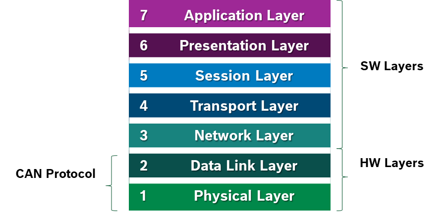
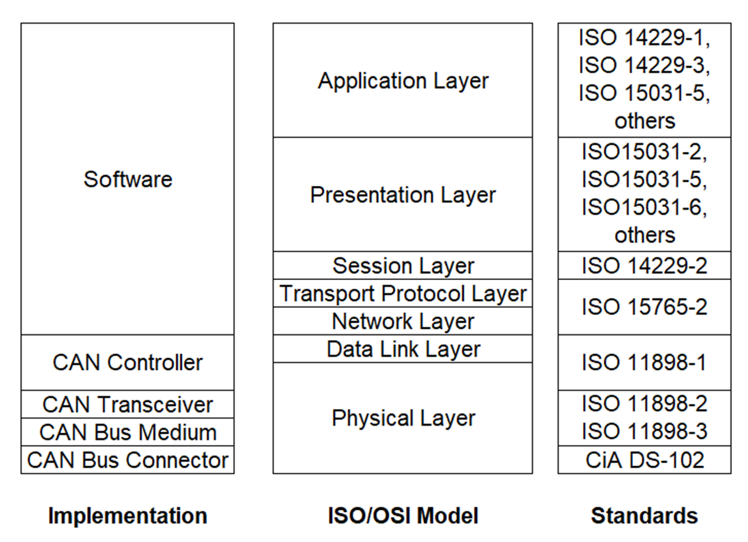
CAN Protocol
The CAN protocol uses the Data Link Layer and the Physical Layer in the ISO - OSI model. There are also some higher-level protocols available for CAN, multi-casting and broadcasting is supported, CAN is most widely used in the automotive and industrial market segments. Typical applications for CAN are motor vehicles, utility vehicles, and industrial automation.
CAN Physical Layer
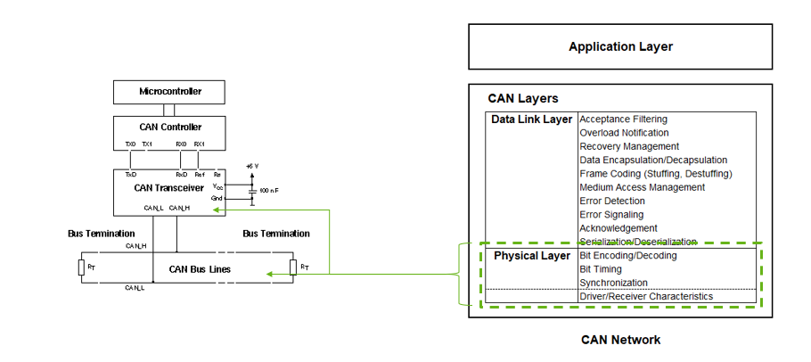
CAN Datalink Layer
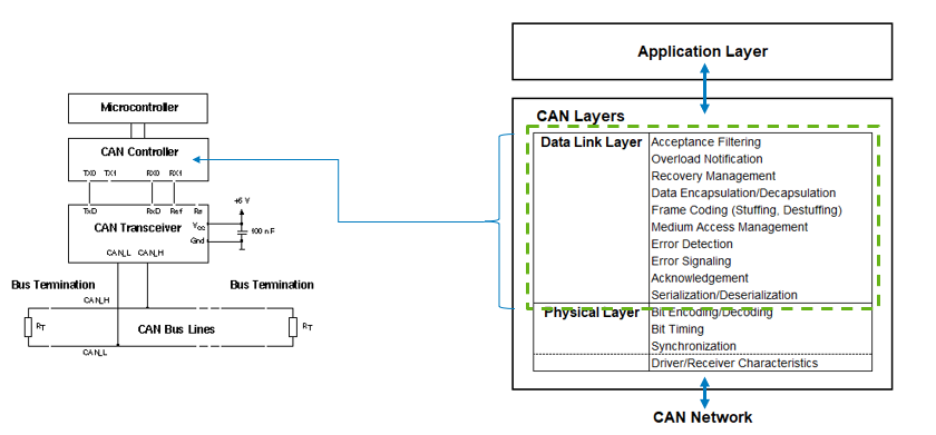
CAN standars
CAN BUS
CAN transceivers handle the bus connection. A CAN transceiver always has two bus pins: one for the CAN high line (CANH) and one for the CAN low line (CANL). This is because physical signal transmission in a CAN network is symmetrical to achieve electromagnetic compatibility, and the physical transmission medium in a CAN network consists of two lines.
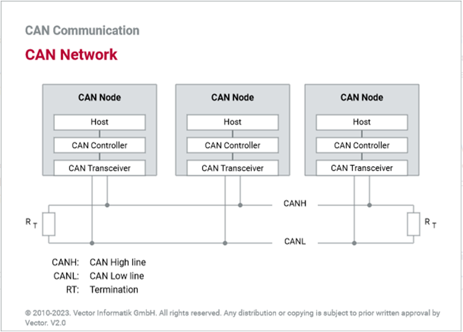
Due to the differential nature of transmission CAN is insensitive to electromagnetic interference, To reduce the sensitivity against electromagnetic interference even more, the bus lines can additionally be shielded.
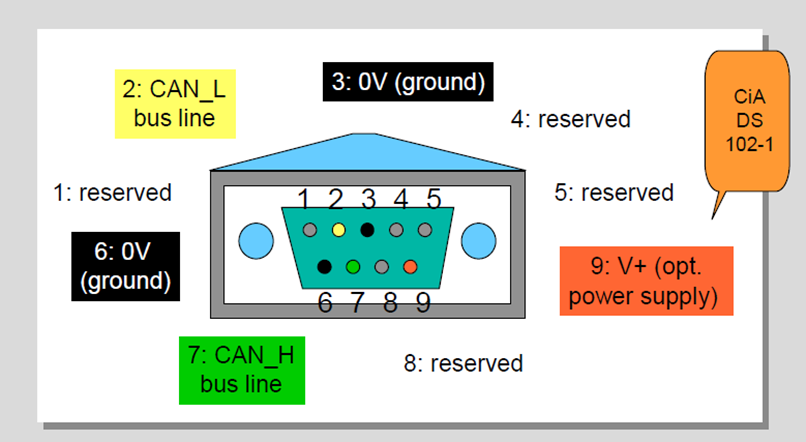
CAN Bus Connector
CAN in Automation user’s group (CiA) created a standard called CiA DS 102-1 which is based on the ISO 11898, 9-pin SUB-D connector for the connection of nodes to the CAN bus lines.
CAN Bus Characteristics
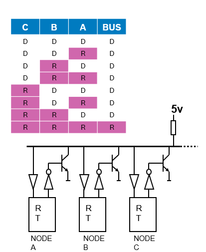
There are two logic states on the bus called “Dominant” and “Recessive”. The bus logic uses a "Wired-AND" mechanism: dominant bit (logic level ’0’) overwrites the Recessive bit (logic level ‘1’). As soon as one node transmits a dominant bit (zero), the bus is in the dominant state. Only if all nodes transmit recessive bits (ones), the Bus is in the recessive state.
CAN Frame
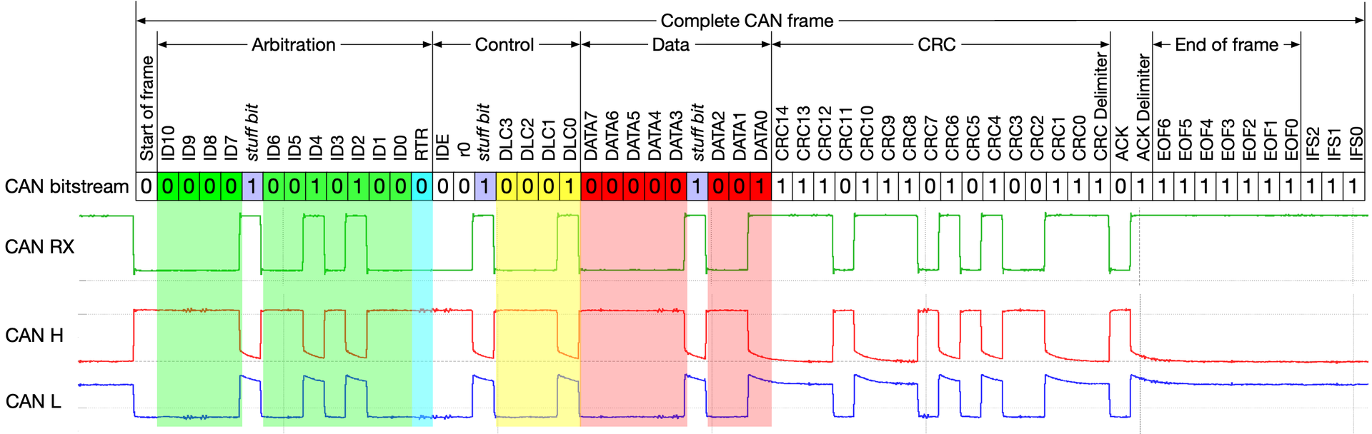
- SoF (Start-of-Frame) bit – Indicates the beginning of a message with a dominant bit
- Arbitration ID – identifies the message and indicates the message’s priority. Frames come in 2 formats: Standard which uses and 11-bit arbitration ID. Extended which uses a 29-bit arbitration ID.
- IDE (Identifier Extension) bit – allows differentiation between standard and extended frames
-
- RTR (Remote Transmission Request) bit – serves to differentiate a remote frame from a data frame. A dominant RTR bit indicates a data frame. A recessive RTR bit indicates a remote frame
- DLC (Data Length Code) – indicates the number of bytes the data field contains
- Data field – contains 0 to 8 bytes of data
- CRC (Cyclic Redundancy Check) - contains 15-bit cyclic redundancy check code and a recessive delimiter bit. The CRC field is used for error detection
- ACK (Acknowledgment) slot – Any CAN controller that correctly receives the message sends an ACL bit at the end of the message. The transmitting node checks for the presence of the ACK bit on the bus and reattempts transmission if no acknowledge is detected
- SRR – Substitute remote request. (Only in extended CAN frame)
- R1, R0 – Reserved bits which must be set dominant , but accepted as either dominant or recessive. (Only in extended CAN frame)
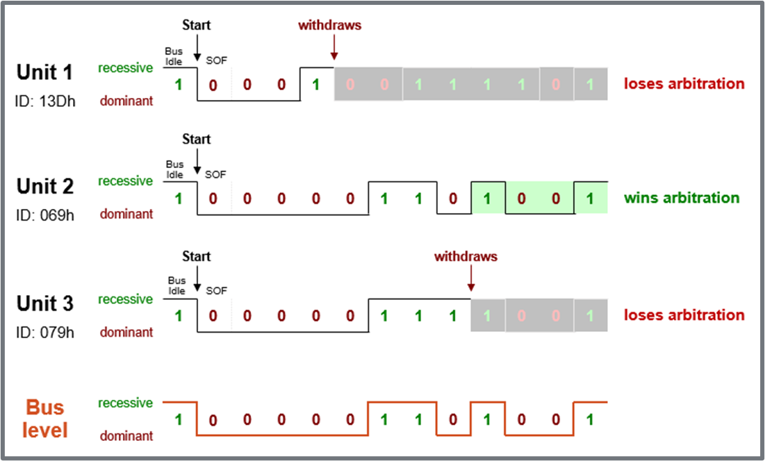
CAN Arbitration
Arbitration means the allocation of bus access rights, in other words, which ECU gets to transmit its message first. This evaluation occurs when several nodes start transmission on the bus at the same time.
Procedure:
- All controllers monitor the bus while transmitting simultaneously.
- A dominant bit (“0”) pulls the bus voltage level to zero.
- When a controller transmits “1”, but observes “0” on the bus, it has lost arbitration.
- Controllers who lost arbitration retreat immediately and retry later.
- Arbitration is won by frame with lowest identifier = highest priority.
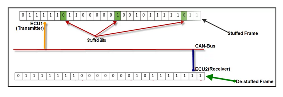
CAN Bit Stuffing
The idea behind bit stuffing is to provide a guaranteed edge on the signal so the receiver can resynchronize with the transmitter before minor clock discrepancies between the two nodes can cause a problem.
More than 5 consecutive bits of the same polarity in CAN frame between the start of Frame(SOF) to CRC field is considered as a faulty frame on CAN Bus and it signaled as stuff error on CAN line.
How does Bit Stuffing work?
- After five consecutive bits of same polarity, insert one bit of reverse polarity.
- CRC code is calculated before bit stuffing is done.
- Bit stuffing is done by the sender directly before transmission.
- De-stuffing is done by the receiver directly after reception.
- CRC code check is done after de-stuffing the frame.
- Bit stuffing is applied to part of the frame from SOF to CRC field.
CAN Error Types
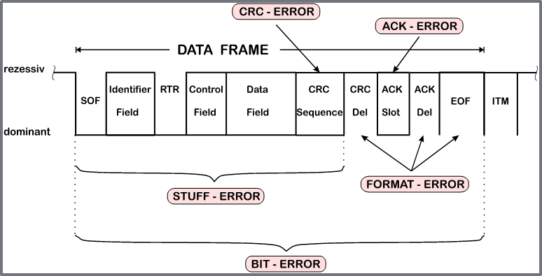
- CRC Calculated and received CRC Checksum must match
- ACK A frame must be Acknowledged by at least one other node (otherwise ACK-Error)
- Form Frame integrity is not preserved, No dominant bits allowed in CRC Delimiter, ACK Delimiter, End of Frame, Intermission (Form Error)
- Bit Monitoring A transmitted bit must be correctly read back from the CAN bus (otherwise Bit Error)
- Bit stuffing 6 consecutive bits with same polarity are not allowed between Start Of Frame and CRC Delimiter (otherwise Bit Stuffing Error)
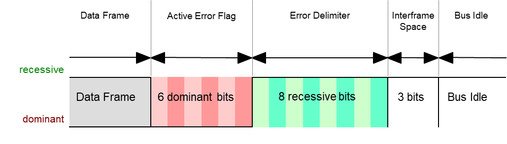
CAN Error Manager
Immediately after an error detection, an Error Frame is transmitted. There is no bit stuffing applied to Error Frames. Other receivers are instantly informed that an error has occurred (unless they already found out).
Yocto Introduction
More information can be found on the official project website: Yocto Official Documentation.
What is Yocto?
First of all, you have to understand that this is not a Linux distribution. It is an open-source project that provides developers with useful tools such as software stacks, layers, templates, and methods, to create a custom Linux-based system from scratch for different hardware architectures, this allows developers to boot on different embedded hardware, making embedded Linux simpler and more accessible.
Why is this important?
The platform we will work on (Automotive Grade Linux) is based on this project using the same tools and some compatibility layers, so it is important first to understand the basics of Yocto and then apply this to AGL.
Compatibility
As an open project, managed by the Linux Foundation, it can support multiple architectures including:
- x86 (32/64 bits)
- PPC
- ARM
- MIPS
Main components
The Yocto project works thanks to a collection of multiple components, including parts of another project called OpenEmbedded, tools such as:
- Bitbake
- OpenEmbedded-Core
- Metadata
The integration of the OpenEmbedded tools and the Yocto components make up the Poky platform, we can see it as an enhanced Buildroot.
To develop software
For adding a single executable file, a toolchain, source files and instructions to compile are sufficient. However, for entire projects that we need dependencies to compile and run, this becomes more complex and we will need additional steps that will form a whole recipe from which variants could be derived depending on the target hardware architecture. To interpret and execute these recipes we will use a Bitbake tool.
Start with Yocto
The first thing to do is to initialize a new environment within the project and edit the conf/local. conf file in which we can choose the target hardware by means of the MACHINE variable before compiling the project by means of bitbake. Unlike similar projects Yocto stands out in the ease of adding new recipes or modify existing ones, for this we use recipe files that usually with the extension . bb (hello. bb), and to add something to this recipe we use the extension . bbappend keeping the name of the original file (hello. bbappend).
Getting Started
Before build
1. At least 90 Gbytes of free disk space.
2. At least 8 Gbytes of RAM.
3. Runs a supported Linux distribution (Supported Linux Distrubutions):
- Fedora
- openSUSE
- CentOS
- Debian
- Ubuntu
4. Install the next tools:
- Git 1.8.3.1 or greater
- tar 1.28 or greater
- Python 3.8.0 or greater.
- gcc 8.0 or greater.
- GNU make 4.0 or greater
5. Install QEMU emmulator:
```
$ sudo apt update && upgrade
$ sudo apt install libvirt-daemon
$ sudo systemctl enable libvirtd
$ sudo systemctl start libvirtd
$ sudo apt install qemu-kvm
```
6. Build host packages:
``` $ sudo apt install gawk wget git diffstat unzip texinfo gcc build-essential chrpath socat cpio python3 python3-pip python3-pexpect xz-utils debianutils iputils-ping python3-git python3-jinja2 libegl1-mesa libsdl1.2-dev python3-subunit mesa-common-dev zstd liblz4-tool file locales ```
``` $ sudo locale-gen en_US.UTF-8 ```
Install Poky:
Poky is the reference operating system distribution built with Yocto Project tools, and OpenEmbedded is a build framework of recipes and packages. The Yocto Project uses Poky to build images (kernel, system, and application software) for targeted hardware, and OpenEmbedded supports many hardware architectures with cross-compilation infrastructure. The community uses it to validate Yocto Project features and functionality, but it also serves as example for any user who builds their own custom distribution.
1. Overview
To build poky we use the bitbake tool wich handles the parsing and execution of the following data files:
- Recipes: Provides details about particular pieces of software
- Class Data: How to build a Linux kernel
- Configuration Data: Machine-specific settings, policy decisions, etc. Acts a the glue to bind everithing together. Bitbake knows how to combine multiple data sources together and refers to each data source as a layer.
2. Download poky
You can direct download the compress file from oficcial page or clone de code repositorie from git using the path specificted in the same page: Download Poky.
3. First time running a build
- Go to the poky folder:
cd poky - Fist you must set the enviromment using the following command:
$ source poky-init-build-env [build_dir]
The build_dir is the dir containing all the build's object files. The default build dir is poky-dir/build. A different build_dir can be used for each of the targets. For example, ~/build/x86 for a qemux86 target, and ~/build/arm for a qemuarm target. Please refer to poky-init-build-env for more detailed information. - Examine your local configuration file (conf/local.conf): For this example, the defaults are set to build for a qemux86 target, which is suitable for emulation. The package manager used is set to the RPM package manager.
- Build the target using:
$ bitbake <target>
The target is the name of the recipe you want to build. Common targets are the images in meta/recipes-core/images, /meta/recipes-sato/images, etc. Or, the target can be the name of a recipe for a specific piece of software such as busybox. For more details about the standard images available, see the 'Reference: Images' appendix. - Emmulate the result with QEMU:
$ runquemu [option ] [...]Once an image has been built it often needs to be installed. The images/kernels built by Poky are placed in the tmp/deploy/images directory. - Exit QEMU:
Ctrl + C
Recipes
Official page: https://docs.yoctoproject.org/overview-manual/concepts.html#recipies
Recipes files
Recipe files or also known as BB files, are files that contain information and instructions that build tool (bitbake) takes for generating the packages. This information for instructions can be resumed as:
- Descriptive information about package
- Section information
- The recipe version
- The Licience
- Existing dependencies
- Where the source code resides and how to fetch it
- Whether the source code requires any patches, where to find them, and how to apply them.
- How to configure and compile the source code.
- Where on the target machine to install the package or packages created.
Variables for bb files
1. Description
Variable name:
- DESCRIPTION = The variable contains a string value that should provide a package description that will be used by package managers. If not set, this value takes the value of the SUMMARY variable.
2. Section
Variable name:
- SECTION = Here you will define what type of recipe it is, the section in which packages should be categorized, it could be: utilities, applications, graphics, kernel, etc.
3. License
Variable name:
-
LICENCE =
In this variable, you specify the type of license you want to use for your recipe for example: -
MIT
-
BSD
-
GPL
However, you need to provide a license file for your selected licensee in the next variable. If LICENCE = 'CLOSED', then you will not use the next variable.
3.1 License file
Variable name:
- LIC_FILES_CHKSUM =
Here, is where you need to provide a licence file. Note: The license files can be found under poky in meta/files/common-licenses/
4. Source for build
Variable name:
- SRC_URI =
Specify what sources files (local or remote) you want to build.
5. Dependencies for build
Variable name:
- DEPENDS =
This are dependencies on other recipes whose contents (for example shared libraries or headers) are needed by the recipe at build time.
6. Recipe build tasks
Build task
The recipes use task to complete configuring, compiling, and packaging software. A continuation will describe the normal task of building a recipe.
- do_build
- do_compile
- do_configure
- do_deploy
- do_fetch
- do_image
- do_install
- do_package
- do_patch
- do_unpack
6.1 do_install variables
| Sintaxis | Path description |
|---|---|
| bindir | /usr/bin |
| sbindir | /usr/sbin |
| libdir | /usr/lib |
| sysconfdir | /etc |
| servicedir | /srv |
| sharedstatedir | /com |
| localstatedir | /var |
| datadir | /usr/share |
| infodir | /usr/info |
| mandir | /usr/man |
| docdir | /usr/doc |
| systemd_unitdir | /usr/lib/systemd |
| systemd_system_unitdir | /usr/lib/systemd/ system |
| systemd_user_unitdir | /usr/lib/systemd/user |
| includedir | /usr/include |
7. Priority of the recipe
Variable name:
- PRIORITY =
Indicates the importance of a package, this depends on the purpose for which the distribution is being produced. You can set: - "required"
- "standard"
- "extra"
- "optional"
8. WORKDIR variable
It is the pathname of the work directory in which the OpenEmbedded build system builds a recipe.
The WORKDIR directory is defined as:
${TMPDIR}/work/${MULTIMACH_TARGET_SYS}/${PN}/${EXTENDPE}${PV}-${PR}
Example for application recipe
For recipe file with the name: helloworld.bb
    DESCRIPTION = "Program that print Hello World! to standar oputput.
    PRIORITY = "optional"
    SECTION = "Examples"
    LICENSE = "MIT"
    LIC_FILES_CHKSUM = "file://${COMMON_LICENCE_DIR}/MIT;md5=0835ade698e0bcf8506ecda2f7b4f302"
    SRC_URI = "file://helloworld.c"
    S = "${WORKDIR}"
    do_compile() {
    ${CC} ${CFLAGS} ${LDFLAGS} helloworld.c -o helloworld
    }
    do_install() {
    install -d ${D}${bindir}
    install -m 0755 helloworld ${D}${bindir}
    }
.bbappend file
Recipes used to append Metadata to other recipes, there are calls append files, these files use the .bbappend file type. This file is used to modify the recipe file, this should have the same name that the recipe, at the same time bbappend files allow your layer to make additions or changes to the content of another layer's recipe without having to copy the other recipe into your layer.
Being able to append information to an existing recipe not only avoid duplication, also automatically applies recipe changes in a different layer to your layer.
Extending recipes with .bbappend files
It is not necessary to recreate entire recipe files from scratch, you can use . bbappend files to supplement an existing recipe file with new information, providing that the original information in the recipe file, resides in an existing layer.
Systemd recipes
To use systemd services has necessary enabled this in the final image, because this is not enabled by default. Add the next lines to the configuration file local. conf to enable system as a default unit manager.
DISTRO_FEATURES_append = " systemd"
DISTRO_FEATURES_BACKFILL_CONSIDERED += "sysvinit"
VIRTUAL-RUNTIME_init_manager = "systemd"
VIRTUAL-RUNTIME_initscripts = "systemd-compat-units"
Important varibales for systemd recipe
1.inherit systemd
Each target has a name instead of a number, ensure the recipe inherits from the systemd class:
inherit systemd
2. NATIVE_SYSTEMD_SUPPORT = "1"
3. SYSTEMD_AUTO_ENABLE
This variable specifies whether the specified service in SYSTEMD_SERVICE should start automatically or not. By default, the service is enabled to automatically start at boot time as follows:
SYSTEMD_AUTO_ENABLE = "enable"
>Note: you can disable this by setting the variable to "disable"
4. SYSTEMD_SERVICE
This variable specifies the systemd service name for a package.
>Note:You can specify multiples services, each one separated by a space.
SYSTEMD_SERVICE:${PN} = "serviceName.service"
5. SYSTEMD_PACKAGES
This variable locates the systemd unit files when they are not found in the main recipe's package.
By default, this variable is set such that the systemd unit files are assumed to reside in the recipes main package:
SYSTEMD_PACKAGES = "${PN}"
6. FILES
This variable provides a package name override that identifies the resulting package, then provide a space separated list of files or paths that identify the files you want included as part of the resulting package:
FILES:${PN} += "${systemd_unitdir}/system/serviceName.service"
Example for systemd service recipe
SUMMARY = "Systemd example recipe"
DESCRIPTION = "Systemd service example"
LICENSE = "CLOSED"

inherit systemd
NATIVE_SYSTEMD_SUPPORT = "1"
SYSTEMD_AUTO_ENABLE = "enable"
SYSTEMD_SERVICE:${PN} = "serviceName.service"

SRC_URI += "file://serviceName.service"

FILES:${PN} += "${systemd_unitdir}/system/hello.service"

S = "${WORKDIR}"

do_install:append(){
    # Install systemd stuff
    install -d ${D}${systemd_unitdir}/system
    install -m 0644 ${WORKDIR}/hello.service ${D}${systemd_unitdir}/system
}
Control systemd from command line
systemctl status: show the status of all services.
systemctl status <service>: show the status of one service.
systemctl [start|stop] <service>: start or stop a service.
systemctl [enable|disable] <service>: enable or disable a service at boot time.
systemctl list-units: list all available units.
journalctl -a: show all logs for all services.
journalctl -f: show only the last log entries, and keep printing updates as they arrive.
journalctl -u: show only logs from a particular service.
Add bb files into your build
To add recipes files is necessary to modify the file conf/local. conf where it's important to add:
IMAGE_INSTALL_append = " recipe_name"
Activity
For this activity, you must create and include in your bootable image, a service using a git repository.
- You can use the tools listed in this and previous chapters.
- Your service should be initialized by System D automatically
Configuration Files
This file has the .conf extension, here is define the configuration variables that control the build process of the project.
With this kind of files we can configure different areas like machine configuration, distribution, configuration, possible compiler tuning, general common configuration, and user configuration.
The main file is bitbake.conf, which you can find inside of the source tree conf directory of Bitbake.
bitbake.conf
This file is related to the main build tool, Bitbake. This file is the first to be parsed and then the rest of the configuration files.
You can find it in: poky/meta/conf/bitbake.conf.
There are many different sections of which we can point out the following:
- Standard target filesystem paths.
This filesystem paths extensively used in different recipes, this section has different subsections. Don't worry you don't have to change these variables, but you should reference these while developing recipes. - Architecture-dependent build variables Variables to define architecture-dependent metadata, these are prefixed with:
BUILD_
HOST_
TARGET_
SDK_
- Packages default variables.
- General work and output directories in the build system.
- Specific image creation and rootfs population information.
- Build flags and options.
- Download locations and utilities.
- Including the rest of the config files.
local.conf
"Before you start your build process, you should open up the local.conf."
This configuration file contains all the local user configurations for your build environment, any variable set here overrides any variable set elsewhere.
Edit this file to set the MACHINE, which package types you wish to use PACKAGE_CLASSES, and the location from which you want to access downloaded files DL_DIR.
Most significant variables in local.conf
The file is well commented so you should understand almost all variables, then you will be shown some variables that are not specified in the initial document:
-
INHERIT
Causes the named class to be inherited globally, anonymous functions in this inherited class are not executed for the base configuration and in each individual recipes.
Suppose you needed to inherit a class file calledabc.bbclassform a configuration file as follows:
INHERIT += "abc" -
BUILDHISTORY_COMMIT This variable specifies whether or not to commit the build history output in a local Git repository, if set to "1" the local repository will be maintained automatically by the build history class and committee will be created on every build for changes.
BUILDHISTORY_COMMIT ?= "1"
With this the .bbclass file must be located in aclassessubdirectory. -
SSTATE_DIR In this variable, you should define the directory for the shared state cache.
SSTATE_DIR = "$home/docs/exaple/sstate-cache" -
SSTATE_MIRRORS
Configure the system to search other mirror locations for prebuild cache data, this could be a filesystem directory or a remote URL such HTTP or FTP. This location needs to contain the shared state cacheSSTATE_CACHEresults from previous builds. If a mirror uses the same structure as SSTATE_DIR, you need to addPATHat the end as follows example:
SSTATE_MIRRORS ?= "\
    file://.* https://someserver.tld/share/sstate/PATH;downloadfilename=PATH \
    file://.* file:///some-local-dir/sstate/PATH"
- DL_DIR
In this variable you can set the central download directory by the build process to store downloads, this directory is self-maintaining and you should not have to touch it, by default the directory is "downloads" in the build directory. To change this you can specify in the variable as follows:
DL_DIR ?= "$home/exaple/topdir/downloads" - IMAGE_INSTALL
In this variable you can specify the packages to install into an image through the image class. Image recipes setIMAGE_INSTALLto specify the packages to install into an image through image, it's important that when you use this variable, use as follows:
IMAGE_INSTALL:append = " package-name"
>Note: When you define a package name after the quotation marks you have to put a space.
bblayers.conf
Here, are defined the layers, which are directory paths, use BBLAYERS variable to list the layers. This file tells Bitbake what layers you want to consider during the build. The dealt layers considered are the minimally needed by the build system.
To enable you layer, simply add your layer's path to the BBLAYERS variety, the following example shows how to enable your new meta-example layer in the build image:
# POKY_BBLAYERS_CONF_VERSION is increased each time build/conf/bblayers.conf
# changes incompatibly
POKY_BBLAYERS_CONF_VERSION = "2"
BBPATH = "${TOPDIR}"
BBFILES ?= ""
BBLAYERS ?= " \
    /home/user/poky/meta \
    /home/user/poky/meta-poky \
    /home/user/poky/meta-yocto-bsp \
    /home/user/mystuff/meta-example \
    "
machine.conf
Note: You won't fint any file with this name.
Machine is a replacement for the name of your board which you will build the image, for example if you want to build for qemux86-64, your configuration name will be qemux86-64.conf and you could find it at: poky/meta-yocto-bsp/conf/machine/.
All of the machine configurations are done in this file.
- The top level header contains information in tags for documentation:
#@TYPE: Machine
#@NAME: qemux86-64 machine
#@DESCRIPTION:
- The preferred xserver can be used:
PREFERRED_PROVIODER_virtual/xserver ?=
XSERVER ?= "       \
                    \
                    \
                    "
- What extra recipes need to be built?
MACHINE_EXTRA_PRECOMMENDS = " "
- Set image dependencies:
EXTRA_IMAGEDEPENDS += ""
- Architecture-specific configurations
DEFAULTTUNE ?= ""
include conf/machine/include/tune-cortexa8.inc
- Type of filesystem images we want to create
IMAGE_FSTYPES += "tar.bz2 jffs2"
EXTRA_IMAGECMD_jffs2 = "-lnp"
- Serial debug console.
SERIAL_CONSOLE = "115200 ttyO0"
- Set our kernel options to see what recipe should be used for kernel compilation and the kernel version needed to be built.
PREFERRED_PROVIDER_virtual/kernel ?= "linux-yocto"
PREFERRED_VERSION_linux-yocto ?= "3.14%"
- To create another kernel image
KERNEL_IMAGETYPE = "uImage"
KERNEL_DEVICETREE = "am335x-bone.dtb am335x"
KERNEL_EXTRA_ARGS += ""
- Configure most of the aspects of the bootloaders
SPL_BINARY = ""
UBOOT_SUFFIX = ""
UBOOT_MACHINE = ""
UBOOT_ENTRYPOINT = ""
UBOOT_LOADADDRESS = ""
- Determine the features that we want our machine to support.
MACHINE_FEATURES = ""
Bitbake
It is a specific build tool (task executor) for yocto, Its main function is to read the configuration files that define the project, establish what task must be performed, and in which order, in dependencies function and for maximizing the efficiency.
What kind of files support Bitbake
- Recipes (.bb files)
This contains information about a specific software component, and the task instructions depending the project. - Classes (.bbclass)
Information that is important to share between different recipes, for example autotools. - Configurations (.conf)
Define different variables of configuration that control what will do the build image (for example poky), this could include machine specifications, distribution configurations, compiler settings, and user configurations.
Executing Taks
Bitbake executes task according to the provided metadata, which is stored in recipe (.bb) and related recipe (.bbappend), configuration files(.conf) and underlying include (.inc), and in class (.bbclass) files. The metadata provides Bitbake with instructions on what task to run and the dependencies between those tasks.
Layers
Bitbake can combine all of these files in what is denominated as layer.
A layer is a group of reusable components and recipes that are reusable in similar circumstances, for example, a user interface (UI) layer or a database layer. Each of these can be implemented by different development teams without affecting others layers functionality.
The OpenEmbedded build system supports organizing Metadata into multiple layers, which allow to isolate different types of customizations from each other.
Layers Structure
Layers all have a similar structure, these could include additional directories in their structure depending their purpose. These can include any combination of recipes, templates, code, configuration files, and packages. In Linux development, there are three specific layer types:
1. Application-specific
Commonly used to manage applications and packages, and share the next structure:
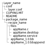
2. Machine-specific
Used to maintain BSP and kernel-related modifications and requirements.
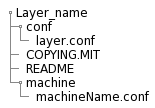
3. Distribution-specific
Used to maintain policies related to your platform project distribution.
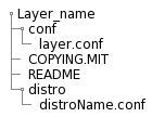
Bitbake-layers
- bitbake-layers create-layer
This command allows us to create a new layer with the career path for recipes. - bitbake-layers add-layer
This command allows us to add the desired layer by specifying at the end of the command, for example:bitbake-layers add-layer meta-example. - bitbake-layers show-layers
This command allows us to check what layers are added to our configuration file for player (you can find this file on your build folder inside of the conf folder).
Execution
The main prop use for running Bitbake is to produce some kind of output such as a single installable package, kernel, software development kit, or even a full board-specific bootable Linux image. Also, you can execute bitbake command with different options, for example: to compile a single recipe, capture or clear data, or simply return information about the execution environment. >Note: Before executing Bitbake, you should check your configuration file local. conf, to corroborate some specific variables that could cause some damage in your build if these don't have a good definition.
Activity
Create and include a new layer to your booting image using only bitbake as your tool, you shouldn't modify the conf files by hand, and run the command to create the image after you test this in a virtual machine.
Devtool
Official documentation: Devtool
This command-line tool provides a number of features that help you build, test, and package software working with yocto.
The devtool command line is organized similarly to GIT, where it has a number of sub-commands for each function.
You can run devtool --help to see all the commands.
Workspace and extensible SDK
To work with devtool command-line it is needed use a "Workspace" layer in which to accomplish build. This layer is not specific to any single devtool command but is rather a common working area used across the tool.
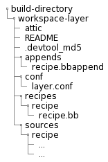
attic - A directory created if devtool believes it must preserve anything when you run "devtool reset". For example, if you run "devtool add", make changes to the recipe, and then run "devtool reset", devtool takes notice that the file has been changed and moves it into the attic should you still want the recipe.
README - Provides information on what is in workspace layer and how to manage it.
.devtool_md5 - A checksum file used by devtool.
appends - A directory that contains *.bbappend files, which point to external source.
conf - A configuration directory that contains the layer.conf file.
recipes - A directory containing recipes. This directory contains a folder for each directory added whose name matches that of the added recipe. devtool places the recipe.bb file within that sub-directory.
sources - A directory containing a working copy of the source files used when building the recipe. This is the default directory used as the location of the source tree when you do not provide a source tree path. This directory contains a folder for each set of source files matched to a corresponding recipe.
devtool add
Assits in adding new software to be built.
- Add application
Generates a new recipe based on existing source code, it is flexible enough to allow you to extract source code into both the workspace or separate local Git repository.
1.1 Generate the new recipe:devtool add recipe example.
1.2 Edit the recipe:devtool edit-recipe example.
1.3 Build the recipe:devtool build example
1.4 Rebuild the image:devtool build-image image_example
1.5 Deploy the build output:devtool deploy-target.
1.6 Finish your work with the recipe:devtool finish recipe layer.
Activity
For this chapter you should:
- Create a new recipe
- Modify the source built by a recipe
- Upgrade a recipe to a new version
Virtual CAN for AGL
AGL and WSL VCAN connectivity
Here is the architecture overview for virtual CAN connectivity between AGL and WSL

Enable VCAN in WSL
WSL by defualt doesn't have VCAN enable, the job now is get the WSL kernel source code (same version we have), enable VCAN from configuration and generate a new WSL Kernel version with VCAN support for our Project, Next are the commands you need follow to complete this activity
Get actual WSL Kernel version
$ uname -r
Output:
- $ uname -r 5.15.90.1-microsoft-standard-WSL2
Create a new folder inside your home folder(example \home\user\WSLkernel) and execute below command
$ git clone https://github.com/microsoft/WSL2-Linux-Kernel

$ cd WSL2-Linux-Kernel
Now we need use same WSL kernel version you get previously
$ git checkout `WSL-version`
Example: $ git checkout linux-msft-wsl-5.15.90.1
Is time to start with the configuration, then create a config backup of your configuration
$ cat /proc/config.gz | gunzip > .config
Run below commands
$ make prepare modules_prepare

$ make menuconfig
The second command will open Linux Kernel Menu where you will need navigate and enable vcan
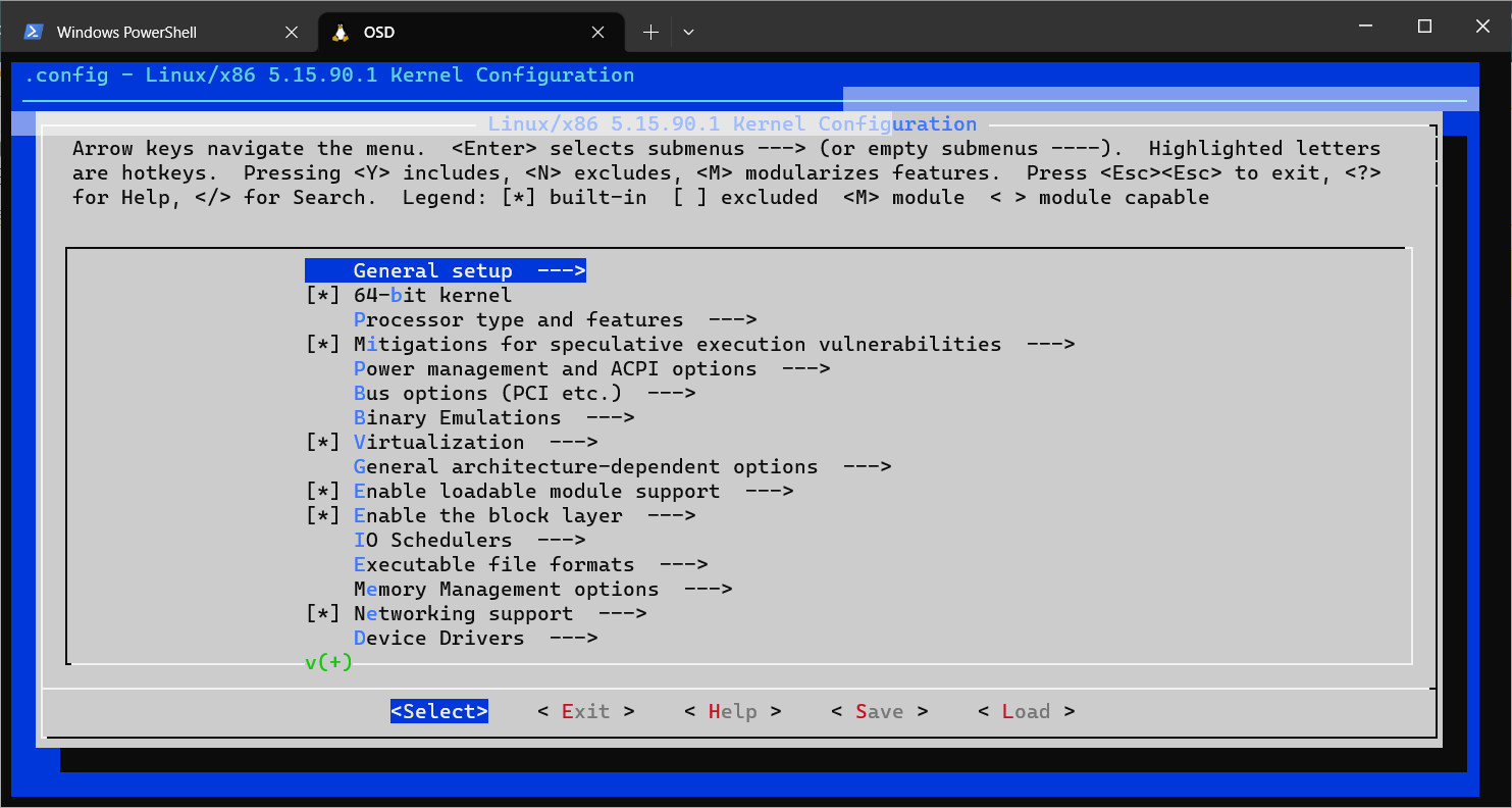
VCAN path and their dependency from Kernel configuration
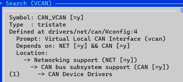
VCAN Configuration
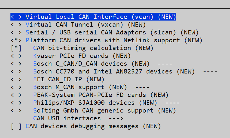 Once you complete the configuration change, save your changes before exit
Note: Is possible also change the configuration without Kernel menu, this is possible editing /proc/config file but you need know what are you are doing there
Now is time to build the new kernel with the new configration
$ make modules
Once previous command complete successfully, need install the new set of modules
# make modules_install
To ensure the new modules are available please take a look in /lib/modules folder, inside you should see a new file like below
$ls /lib/modules
5.15.90.1-microsoft-standard-WSL2+
Copy the new kernel to Windows folder we will need to boot WSL with this kernel
cp vmlinux /mnt/c/Users/"myuser"/WSLKernel
Is time to stop WSL and change the configuration to boot WSL from new Kernel
wsl --shutdown
Also we need update the .wslconfig from C:\Users"myuser", open the file and add the below line just replace the path from the kernel file you copy from WSL
#Use own kernel with socketCAN enable
kernel=C:\\Users\\"myuser"\\WSLKernel\\vmlinux2
Open WSL and once boot is complete check the actual version
$ uname -r
Output will be like:
- $ uname -r 5.15.90.1-microsoft-standard-WSL2+
Run below commands to enable module component in your WSL
$ sudo modprobe vcan
Now create a virtual CAN network interface using this command
$ sudo ip link add dev can0 type vcan
Install CAN Tools in WSL
Can-utils is a command line Linux utility that contains basic tools which can display, record, generate and replay CAN traffic. Along with these basic operations we can also calculate busload, convert log files and it also contain ISO 15765-2:2016 tools.
Install CAN Tools for test purpose with next command:
sudo apt install can-utils
CANdevStudio
CANdevStudio aims to be cost-effective replacement for CAN simulation software. It can work with variety of CAN hardware interfaces (e.g. Microchip, Vector, PEAK-Systems) or even without it (vcan and cannelloni) . CANdevStudio enables to simulate CAN signals such as ignition status, doors status or reverse gear by every automotive developer
Download the latest release (deb format) from https://github.com/GENIVI/CANdevStudio/releases, below is an example
wget https://github.com/GENIVI/CANdevStudio/releases/download/v1.2.2/CANdevStudio-1.2.2-Linux-standalone.deb
Once you have the deb file Install with next commands
sudo apt install /path/of/installation/file/CANdevStudio-1.2.2-Linux-standalone.deb
Once installation is completed lunch CANdevStudio run CANdevStudio.sh script
/usr/CANdevStudio/CANdevStudio.sh > /dev/null 2>&1 &
Will come first CANdevStudio Windows like this

Here you have to create a new project
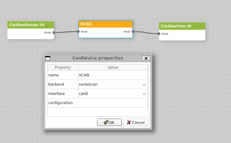
Add CAN load with CanRawSender block
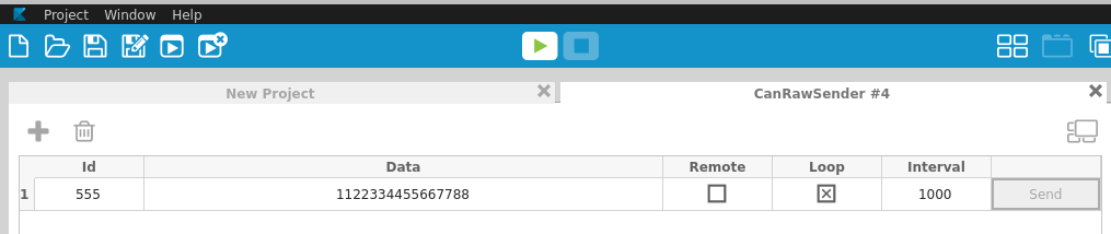
Check CAN log using candump tool (part of can-utils installed in previous section)
AGL kernel Configuration for CAN connectivity
This section will provide the steps to config the AGL kernel to add CAN bus with specific device in order to connect with HOST machine (WSL). Guess require CAN configuration like in real usage
As previous kernel configuration we need open kernel menu
$ bitbake linux-yocto -c menuconfig
Now add Network Support for CAN, CAN Subsystem support, bitrate calculation support and kvaser_pci device for new Kernel
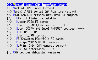
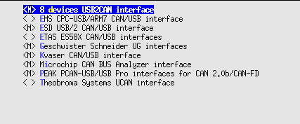
Save new configuration and build your Demo Project
Enable VCAN in QEMU
An example of CAN connection between host with AGL (guess) is available in this page (CAN Bus Emulation): CAN Bus Emulation
Base on previous information we add the QEMU configuration for can0 and kvaser_pci device, below is the output command
/Folder/Path/of/your/BuildFolder/tmp/work/x86_64-linux/qemu-helper-native/1.0-r1/recipe-sysroot-native/usr/bin/qemu-system-x86_64 \
-device virtio-net-pci,netdev=net0,mac=52:54:00:12:35:02 \
-netdev user,id=net0,hostfwd=tcp::2222-:22,hostfwd=tcp::2323-:23,tftp=/AGL/UniversityNF/BUniversityClusterDemo/tmp/deploy/images/qemux86-64 -object rng-random,filename=/dev/urandom,id=rng0 \
-device virtio-rng-pci,rng=rng0 \
-drive file=/AGL/UniversityNF/BUniversityClusterDemo/tmp/deploy/images/qemux86-64/agl-cluster-university-qemux86-64-20230912224834.rootfs.ext4,if=virtio,format=raw -vga vmware \
-display default,show-cursor=on -usb \
-device usb-tablet -device virtio-rng-pci -vga virtio  -vnc :0 \
-machine q35 -cpu qemu64,+ssse3,+sse4.1,+sse4.2,+popcnt -smp 4 \
-m 2048 \
-serial mon:stdio -serial null  \
-kernel /AGL/UniversityNF/BUniversityClusterDemo/tmp/deploy/images/qemux86-64/bzImage \
-append 'root=/dev/vda rw  ip=dhcp console=ttyS0 console=ttyS1 oprofile.timer=1 tsc=reliable no_timer_check rcupdate.rcu_expedited=1 console=ttyS0,115200n8 quiet ' \
-object can-bus,id=canbus0 \
-object can-host-socketcan,id=canhost0,if=can0,canbus=canbus0 \
-device kvaser_pci,canbus=canbus0
Demo
Run Host and AGL with CAN configuration described before.
Open CANdevStudio on Host and prepare a project to transmit different messages
Prepare AGL to test CAN network
ip link set can0 type can bitrate 1000000
ip link set can0 up
Open candump tool for can0 you should see the messages sent by CANdevStudio from WSL(HOST) in AGL